Nissan Rogue Service Manual: Air cleaner filter
Exploded view
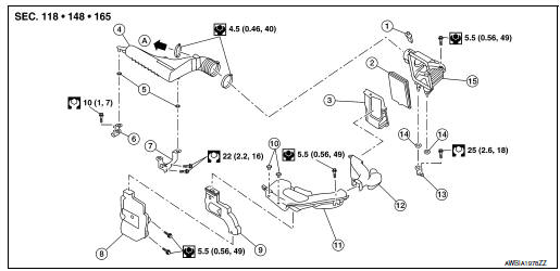
- Mass air flow sensor
- Air cleaner filter
- Air cleaner case (lower)
- Air duct assembly
- Grommet
- Resonator bracket (front)
- Resonator bracket (rear)
- Resonator
- Air duct
- Mounting clip
- Air duct assembly
- Air duct assembly
- Air cleaner bracket
- Grommet
- Air cleaner case (upper)
- To Electric throttle control actuator
Removal and installation
CHANGING THE AIR CLEANER FILTER
- Remove air duct assembly from air cleaner case (upper).
- Open the air cleaner case.
- Remove the air cleaner filter.
- Install a new air cleaner filter.
- Close the air cleaner case.
- Secure the air cleaner case clips.
INSPECTION AFTER REMOVAL
Examine the air cleaner filter for stains, clogging, or damage.
- Remove dirt and foreign objects (such as dead leaves) on air cleaner filter surface and inside cleaner case.
- If clogging or damage is observed, replace the air cleaner filter.
CAUTION: Do not clean the viscous paper type air cleaner filter by blowing as there is a risk of deterioration of its performance.
MAINTENANCE INTERVAL
Refer to MA-7, "Introduction of Periodic Maintenance".
 Drive belts
Exploded view
Generator pulley
Water pump pulley
Drive belt auto-tensioner
Crankshaft pulley
A/C compressor pulley
Drive belt retainer boss
View A
&nbs ...
 Spark plug
Exploded view
Ignition coil
Spark plug
Rocker cover
Removal and installation
REMOVAL
Remove air duct assembly.
Remove ignition coil. Refer to EM-36, "Ex ...
Other materials:
Precaution
Precaution for Supplemental Restraint System (SRS) "AIR BAG" and "SEAT
BELT
PRE-TENSIONER"
The Supplemental Restraint System such as “AIR BAG” and “SEAT BELT PRE-TENSIONER”,
used along
with a front seat belt, helps to reduce the risk or severity of injury to the
...
P0778 pressure control solenoid B
DTC Description
DTC DETECTION LOGIC
DTC
CONSULT screen terms
(Trouble diagnosis content)
DTC detection condition
P0778
PC SOLENOID B
(Pressure Control Solenoid “B” Electrical)
When all of the following conditions are satisfied and this state is
maintained
...
System description
SYSTEM
System Description
SYSTEM DIAGRAM
SYSTEM DESCRIPTION
The BCM has a CAN gateway function.
The BCM communicates between two CAN communication circuits.
The BCM selects and transmits only necessary information.
DIAGNOSIS SYSTEM (CAN GATEWAY)
CONSULT Function
...