Nissan Rogue Service Manual: Component parts
Component Parts Location
- Instrument lower panel LH
|
No. |
Component |
Function |
| 1 | Combination meter |
Refer to MWI-6, "METER SYSTEM : Component Parts Location" for detailed installation location. |
| 2 | TCM |
Refer to TM-12, "CVT CONTROL SYSTEM : Component Parts Location" for detailed installation location. |
| 3 | ECM |
Refer to EC-14, "Component Parts Location" for detailed installation location. |
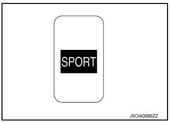
| 4 | SPORT mode switch | Refer to DMS-4, "SPORT Mode Switch". |
SPORT Mode Switch
- The SPORT mode switch is installed to the instrument lower finisher.
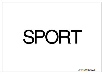
- When the SPORT mode indicator lamp on the combination meter is OFF and the SPORT mode switch is pressed, the SPORT mode is active and the SPORT mode indicator lamp is ON.
- When the SPORT mode indicator lamp on the combination meter is ON and the SPORT mode switch is pressed, the SPORT mode is cancelled and the SPORT mode indicator lamp is OFF.
SPORT Mode Indicator Lamp
DESIGN/PURPOSE
The SPORT mode indicator lamp inform the driver that the vehicle is in SPORT mode.
BULB CHECK
Not applicable
SYSTEM DIAGRAM
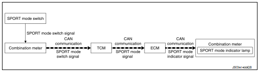
SIGNAL PATH
- TCM receives SPORT mode switch signal (ON/OFF) from combination
meter via CAN communication.
Based on the signal, TCM transmits SPORT mode signal to ECM via CAN communication.
- ECM transmits SPORT mode indicator signal to combination meter via CAN communication. Based on the signal, combination meter illuminates SPORT mode indicator lamp.
LIGHTING CONDITION
When all of the following conditions are satisfied
- Ignition switch: ON
- The SPORT mode switch is pressed when the SPORT mode indicator lamp is OFF
SHUTOFF CONDITION
When any of the condition listed below is satisfied.
- Ignition switch: Other than ON
- The SPORT mode switch is pressed when the SPORT mode indicator lamp is ON.

 System
SPORT MODE CONTROL
SPORT MODE CONTROL : System Description
SYSTEM DIAGRAM
SYSTEM DISCRIPTION
TCM receives SPORT mode switch signal (ON/OFF) from combination
meter via CAN communica ...
Other materials:
Basic inspection
DIAGNOSIS AND REPAIR WORKFLOW
Work Flow
OVERALL SEQUENCE
DETAILED FLOW
1.GET INFORMATION FOR SYMPTOM
Get detailed information from the customer about the symptom (the condition
and the environment when the
incident/malfunction occurred).
>> GO TO 2.
2.CONFIRM THE SYMPTOM
Try t ...
Periodic maintenance
REAR WHEEL HUB AND HOUSING
Inspection
INSPECTION
Make sure the conditions (looseness, back lash) of each component and
component conditions (wear, damage)
are normal.
WHEEL HUB AND BEARING INSPECTION
Move wheel hub and bearing in the axial direction by hand. Make
sure there is no ...
CAN system (type 7)
MAIN LINE BETWEEN IPDM-E AND DLC CIRCUIT
Diagnosis Procedure
1.CHECK CONNECTOR
Turn the ignition switch OFF.
Disconnect the battery cable from the negative terminal.
Check the following terminals and connectors for damage, bend and
loose connection (connector side
an ...