Nissan Rogue Service Manual: Front wiper motor lo circuit
Component Function Check
1.CHECK FRONT WIPER LO OPERATION
 CONSULT ACTIVE TEST
- Select FR WIPER of BCM (WIPER) active test item.
- Check front wiper operation.
LO : Front wiper (LO) operation
OFF : Front wiper OFF
Is the inspection result normal? YES >> Front wiper motor LO circuit is normal.
NO >> Refer to WW-36, "Diagnosis Procedure".
Diagnosis Procedure
Regarding Wiring Diagram information, refer to WW-22, "Wiring Diagram".
1. CHECK FRONT WIPER MOTOR FUSE
- Turn the ignition switch OFF.
- Check that the following fuse is not blown.

Is the fuse blown? YES >> Replace the fuse after repairing the affected circuit.
NO >> GO TO 2.
2. CHECK FRONT WIPER MOTOR (LO) OUTPUT VOLTAGE
- Turn the ignition switch ON.
- Select FR WIPER of BCM (WIPER) active test item.
- While performing the active test, check voltage between IPDM E/R harness connector and ground.
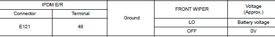
Is the inspection result normal? YES >> GO TO 3.
NO >> Replace IPDM E/R. Refer to PCS-35, "Removal and Installation".
3. CHECK FRONT WIPER MOTOR (LO) OPEN CIRCUIT
- Turn the ignition switch OFF.
- Disconnect IPDM E/R and front wiper motor.
- Check continuity between IPDM E/R harness connector and front wiper motor harness connector.
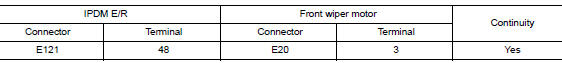
Is the inspection result normal? YES >> Replace front wiper motor. Refer to WW-67, "Removal and Installation".
NO >> Repair or replace harness.
 Wiper and washer fuse
Description
Diagnosis Procedure
1. CHECK FUSES
Check that the following fuses are not blown.
Is the fuse blown?
YES >> Replace the fuse after repairing the affected circuit.
NO & ...
 Front wiper motor HI circuit
Component Function Check
1.CHECK FRONT WIPER HI OPERATION
CONSULT ACTIVE TEST
Select FR WIPER of BCM (WIPER) active test item.
Check front wiper operation.
HI : Front wiper (HI ...
Other materials:
P0715 input speed sensor A
DTC Description
DTC DETECTION LOGIC
DTC
CONSULT screen terms
(Trouble diagnosis content)
DTC detection condition
P0715
INPUT SPEED SENSOR A
(Input/Turbine Speed Sensor A Circuit)
When 1 is satisfied and any of 2, 3 or 4 is satisfied:
When the following c ...
S connector circuit
Description
The starter motor magnetic switch is supplied with power when the ignition
switch is turned to the START position
while the selector lever is in the P (Park) or N (Neutral) position.
Diagnosis Procedure
Regarding Wiring Diagram information, refer to STR-7, "Wiring Diagram" ...
Supplemental air bag warning labels
SRS Air Bag Warning Labels
SRS Air Bag Warning Labels
The warning labels are located on the surface
of the sun visor.
Warning labels about the supplemental frontimpact
air bag system are placed in the vehicle as
shown in the illustration.
WARNINGExtreme Hazard! Do not us ...