Nissan Rogue Owners Manual: Head restraints/Headrests
| WARNING Head restraints/headrests supplement the other vehicle safety systems. They may provide additional protection against injury in certain rear end collisions. Adjustable head restraints/headrests must be adjusted properly, as specified in this section. Check the adjustment after someone else uses the seat. Do not attach anything to the head restraint/headrest stalks or remove the head restraint/headrest. Do not use the seat if the head restraint/headrest has been removed. If the head restraint/headrest was removed, reinstall and properly adjust the head restraint/headrest before an occupant uses the seating position. Failure to follow these instructions can reduce the effectiveness of the head restraints/headrests. This may increase the risk of serious injury or death in a collision. |
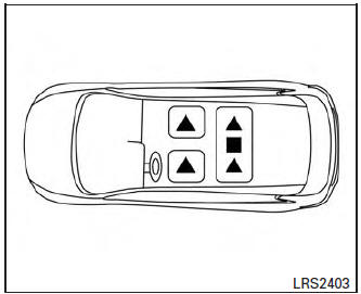
2nd row seating
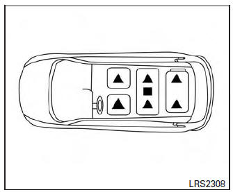
3rd row seating (if so equipped)
The illustration shows the seating positions equipped with head restraints/headrests.
 Indicates the seating position is
equipped with
a head restraint.
Indicates the seating position is
equipped with
a head restraint.
 Indicates the seating position is
equipped with
a headrest.
Indicates the seating position is
equipped with
a headrest.
+ Indicates the seating position is not equipped with a head restraint or headrest (if applicable).
- Your vehicle is equipped with a head restraint/headrest that may be integrated, adjustable or non-adjustable.
- Adjustable head restraints/headrests have multiple notches along the stalk(s) to lock them in a desired adjustment position.
- The non-adjustable head restraints/headrests have a single locking notch to secure them to the seat frame.
- Proper Adjustment:
- For the adjustable type, align the head restraint/headrest so the center of your ear is approximately level with the center of the head restraint/headrest.
- If your ear position is still higher than the recommended alignment, place the head restraint/headrest at the highest position.
- If the head restraint/headrest has been removed, ensure that it is reinstalled and locked in place before riding in that designated seating position.
Adjustable head restraint/headrest components
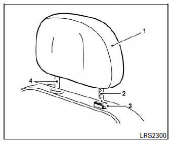
Adjustable head restraint/headrest components
- Removable head restraint/headrest
- Multiple notches
- Lock knob
- Stalks
Non-adjustable head restraint/headrest components
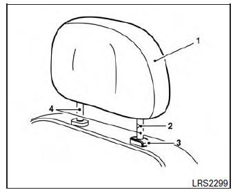
Non-adjustable head restraint/headrest components
- Removable head restraint/headrest
- Single notch
- Lock knob
- Stalks
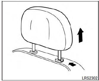
Remove
Remove
Use the following procedure to remove the head restraint/headrest:
- Pull the head restraint/headrest up to the highest position.
- Push and hold the lock knob.
- Remove the head restraint/headrest from the seat.
- Store the head restraint/headrest properly in a secure place so it is not loose in the vehicle.
- Reinstall and properly adjust the head restraint/headrest before an occupant uses the seating position.
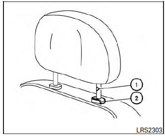
Install
Install
- Align the head restraint/headrest stalks with the holes in the seat. Make sure that the head restraint/headrest is facing the correct direction. The stalk with the notch (notches) 1 must be installed in the hole with the lock knob 2 .
- Push and hold the lock knob and push the head restraint/headrest down.
- Properly adjust the head restraint/headrest before an occupant uses the seating position.
 Flexible seating
WARNING
Never allow anyone to ride in the cargo
area or on the rear seats when they are
in the fold-down position. In a collision,
people riding in these areas without
...
 Adjust
For adjustable head restraint/headrest
Adjust the head restraint/headrest so the center
is level with the center of your ears. If your ear
position is still higher than the recommended
alignment ...
Other materials:
Key switch signal circuit (without intelligent key)
Description
Transmits a key switch signal to the BCM.
Component Function Check
1. CHECK BCM INPUT SIGNAL
Select "Data Monitor" for "BCM" and check the "KEY ON SW" monitor value.
Is the inspection result normal?
YES >> Inspection End.
NO >> Refer ...
Periodic maintenance
REAR WHEEL HUB AND HOUSING
Inspection
INSPECTION
Make sure the conditions (looseness, back lash) of each component and
component conditions (wear, damage)
are normal.
WHEEL HUB AND BEARING INSPECTION
Move wheel hub and bearing in the axial direction by hand. Make
sure there is no ...
System description
COMPONENT PARTS
Component Parts Location
No.
Component
Description
1
Push-button ignition
switch1
Push-button ignition switch (push switch) is pressed (ON), and
transmits status signal to BCM
and IPDM E/R.
Ignition switch2
Ignition ...