Nissan Rogue Service Manual: P0131 A/F sensor 1
DTC Description
DTC DETECTION LOGIC
To judge the malfunction, the diagnosis checks that the A/F signal computed by ECM from the A/F sensor 1 signal is not inordinately low.
| DTC No. | CONSULT screen terms (Trouble diagnosis content) | DTC detecting condition |
| P0131 | A/F SENSOR1 (B1) (O2 sensor circuit low voltage bank 1 sensor 1) | The A/F signal computed by ECM from the A/F sensor 1 signal is constantly approx. 0 V. |
POSSIBLE CAUSE
- Harness or connectors (A/F sensor 1 circuit is open or shorted.)
- A/F sensor 1
FAIL-SAFE
Not applicable
DTC CONFIRMATION PROCEDURE
1.PRECONDITIONING
If DTC Confirmation Procedure has been previously conducted, always perform the following procedure before conducting the next test.
- Turn ignition switch OFF and wait at least 10 seconds.
- Turn ignition switch ON.
- Turn ignition switch OFF and wait at least 10 seconds.
TESTING CONDITION: Before performing the following procedure, confirm that battery voltage is more than 10.5 V at idle.
>> GO TO 2.
2.CHECK A/F SENSOR FUNCTION
 With CONSULT
- Start engine and warm it up to normal operating temperature.
- Select “A/F SEN1 (B1)” in “DATA MONITOR” mode of “ENGINE” using CONSULT.
- Check “A/F SEN1 (B1)” indication.
 With GST
Follow the procedure “With CONSULT” above.
Is the indication constantly approx. 0 V? YES >> Proceed to EC-231, "Diagnosis Procedure".
NO >> GO TO 3.
3.PERFORM DTC CONFIRMATION PROCEDURE
 With CONSULT
- Turn ignition switch OFF, wait at least 10 seconds and then restart engine.
- Drive and accelerate vehicle to more than 40 km/h (25 MPH) within
20 seconds after restarting engine.
CAUTION: Always drive vehicle at a safe speed.
- Maintain the following conditions for about 20 consecutive seconds.
| ENG SPEED | 1,000 - 3,200 rpm |
| VHCL SPEED SE | More than 40 km/h (25 mph) |
| B/FUEL SCHDL | 1.5 - 9.0 msec |
| Selector lever | Suitable position |
NOTE:
- Keep the accelerator pedal as steady as possible during the cruising.
- If this procedure is not completed within 1 minute after restarting engine at step 1, return to step 1.
- Check 1st trip DTC.
With GST
Follow the procedure “With CONSULT” above.
Is 1st trip DTC detected? YES >> Proceed to EC-231, "Diagnosis Procedure".
NO >> INSPECTION END
Diagnosis Procedure
1.CHECK AIR FUEL RATIO (A/F) SENSOR 1 POWER SUPPLY
- Turn ignition switch OFF.
- Disconnect A/F sensor 1 harness connector.
- Turn ignition switch ON.
- Check the voltage between A/F sensor 1 harness connector and ground.
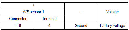
Is the inspection result normal? YES >> GO TO 3.
NO >> GO TO 2.
2.CHECK AIR FUEL RATIO (A/F) SENSOR 1 POWER SUPPLY CIRCUIT
- Turn ignition switch OFF.
- Disconnect IPDM E/R harness connector.
- Check the continuity between A/F sensor 1 harness connector and IPDM E/R harness connector.
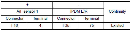
- Also check harness for short to ground.
Is the inspection result normal? YES >> Perform the trouble diagnosis for power supply circuit.
NO >> Repair or replace error-detected parts.
3.CHECK A/F SENSOR 1 INPUT SIGNAL CIRCUIT
- Turn ignition switch OFF.
- Disconnect ECM harness connector.
- Check the continuity between A/F sensor 1 harness connector and ECM harness connector.
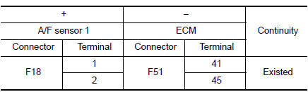
- Check the continuity between A/F sensor 1 harness connector and ground, or ECM harness connector and ground.
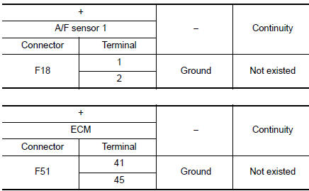
- Also check harness for short to power.
Is the inspection result normal? YES >> GO TO 4.
NO >> Repair or replace error-detected parts.
4.CHECK INTERMITTENT INCIDENT
Perform GI-41, "Intermittent Incident".
Is the inspection result normal? YES >> GO TO 5.
NO >> Repair or replace error-detected parts.
5.REPLACE AIR FUEL RATIO (A/F) SENSOR 1
Replace air fuel ratio (A/F) sensor 1. Refer to EM-29, "Exploded View".
CAUTION:
- Discard any sensor which has been dropped from a height of more than 0.5 m (19.7 in) onto a hard surface such as a concrete floor; use a new one.
- Before installing new sensor, clean exhaust system threads using Oxygen Sensor Thread Cleaner [commercial service tool (J-43897-18 or J43897-12)] and approved Anti-seize Lubricant (commercial service tool)
>> INSPECTION END
 P0130 A/F sensor 1
DTC Description
DTC DETECTION LOGIC
To judge the malfunction, the diagnosis checks that the A/F signal computed
by ECM from the A/F sensor 1
signal fluctuates according to fuel feedback control.
...
 P0132 A/F sensor 1
DTC Description
DTC DETECTION LOGIC
To judge the malfunction, the diagnosis checks that the A/F signal computed
by ECM from the A/F sensor 1
signal is not inordinately high.
DTC No.
CO ...
Other materials:
Intelligent 4WD (if so equipped)
4X4–I SYSTEM OPERATION
WARNING
Do not drive beyond the performance
capability of the tires. Accelerating
quickly, sharp steering maneuvers or
sudden braking may cause loss of control,
even with Intelligent 4WD engaged.
For 4WD equipped vehicles, do not a ...
Brake pedal
Adjustment
BRAKE PEDAL HEIGHT
Remove instrument lower panel LH. Refer to IP-22, "Removal and
Installation".
Disconnect the harness connectors from the stop lamp switch and
brake pedal position switch.
Turn the stop lamp switch and brake pedal position switc ...
Symptom diagnosis
HEAVY TIGHT-CORNER BRAKING SYMPTOM OCCURS
Description
Heavy tight-corner braking symptom occurs when the vehicle is driven and the
steering wheel is turned fully to
either side after the engine is started.
NOTE:
Light tight-corner braking symptom may occur depending on driving conditions.
...