Nissan Rogue Service Manual: P0327, P0328 KS
DTC Description
DTC DETECTION LOGIC
| DTC No. | CONSULT screen terms (Trouble diagnosis content) | DTC detecting condition |
| P0327 | KNOCK SEN/CIRC-B1 (Knock sensor 1 circuit low bank 1 or single sensor) | An excessively low voltage from the knock sensor is sent to ECM. |
| P0328 | KNOCK SEN/CIRC-B1 (Knock sensor 1 circuit high bank 1 or single sensor) | An excessively high voltage from the knock sensor is sent to ECM |
POSSIBLE CAUSE
- Harness or connectors (Knock sensor circuit is open or shorted.)
- Knock sensor
FAIL-SAFE
Not applicable
DTC CONFIRMATION PROCEDURE
1.PRECONDITIONING
If DTC Confirmation Procedure has been previously conducted, always perform the following procedure before conducting the next test.
- Turn ignition switch OFF and wait at least 10 seconds.
- Turn ignition switch ON.
- Turn ignition switch OFF and wait at least 10 seconds.
TESTING CONDITION: Before performing the following procedure, confirm that battery voltage is more than 10 V at idle.
>> GO TO 2.
2.PERFORM DTC CONFIRMATION PROCEDURE
- Start engine and run it for at least 5 seconds at idle speed.
- Check 1st trip DTC.
Is 1st trip DTC detected? YES >> Proceed to EC-293, "Diagnosis Procedure".
NO >> INSPECTION END
Diagnosis Procedure
1.CHECK KNOCK SENSOR GROUND CIRCUIT
- Turn ignition switch OFF.
- Disconnect knock sensor harness connector.
- Disconnect ECM harness connector.
- Check the continuity between knock sensor harness connector and ECM harness connector.
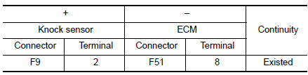
- Also check harness for short to power.
Is the inspection result normal? YES >> GO TO 2.
NO >> Repair or replace error-detected parts.
2.CHECK KNOCK SENSOR INPUT SIGNAL CIRCUIT
- Check the continuity between knock sensor harness connector and ECM harness connector.
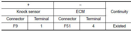
- Also check harness for short to ground and to power.
Is the inspection result normal? YES >> GO TO 3.
NO >> Repair open circuit or short to ground or short to power in harness or connectors.
3.CHECK KNOCK SENSOR
Check the knock sensor. Refer to EC-294, "Component Inspection".
Is the inspection result normal? YES >> GO TO 4.
NO >> Replace knock sensor. Refer to EM-92, "Exploded View".
4.CHECK INTERMITTENT INCIDENT
Refer to GI-41, "Intermittent Incident".
>> INSPECTION END
Component Inspection
1.CHECK KNOCK SENSOR
- Turn ignition switch OFF.
- Disconnect knock sensor harness connector.
- Check resistance between knock sensor terminals as per the following.
NOTE: It is necessary to use an ohmmeter which can measure more than 10 MΩ.
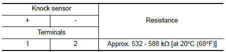
CAUTION: Do not use any knock sensors that have been dropped or physically damaged. Use only new ones. Is the inspection result normal?
YES >> INSPECTION END
NO >> Replace knock sensor. Refer to EM-92, "Exploded View".
 P0300, P0301, P0302, P0303, P0304 misfire
DTC Description
DTC DETECTION LOGIC
When a misfire occurs, engine speed will fluctuate. If the engine speed
fluctuates enough to cause the crankshaft
position (CKP) sensor (POS) signal to vary, E ...
 P0335 CKP sensor (POS)
DTC Description
DTC DETECTION LOGIC
DTC No.
CONSULT screen terms
(Trouble diagnosis content)
DTC detecting conditio
P0335
CKP SEN/CIRCUIT
(Crankshaft position sensor & ...
Other materials:
B0029 side curtain air bag module RH
DTC Logic
DTC DETECTION LOGIC
CONSULT name
DTC
DTC detecting condition
Repair order
CURTAIN AIRBAG MODULE RH CIRCUIT
[OPEN]
B0029
RH side curtain air bag module circuit
is open.
Refer to SRC-57, "Diagnosis Procedure".
CURTA ...
Front wiper does not operate
Description
The front wiper does not operate under any operation conditions.
Diagnosis Procedure
Regarding Wiring Diagram information, refer to WW-22, "Wiring Diagram".
1. CHECK WIPER RELAY OPERATION
CONSULT ACTIVE TEST
Select FR WIPER of BCM (WIPER) active test item.
&nb ...
Lifting point
Special service tool
The actual shapes of Kent-Moore tools may differ from those of special
service tools illustrated here.
Tool number
(Kent-Moore No.)
Tool name
Description
LM4086-0200
( - )
Board on attachment
LM4519-0000
( - )
Safety stan ...