Nissan Rogue Service Manual: P0520 EOP sensor
DTC Description
DTC DETECTION LOGIC
| DTC No. | CONSULT screen terms (Trouble diagnosis content) | DTC detecting condition |
| P0520 | EOP SENSOR/SWITCH (Engine oil pressure sensor/switch circuit) | Signal voltage from the EOP sensor remains at more than 5.02 V / less than 0.3 V for 5 seconds or more. |
POSSIBLE CAUSE
- Harness or connectors (EOP sensor circuit is open or shorted.)
- Engine oil level abnormality
- EOP sensor
- Sensor power supply 2 circuit
FAIL-SAFE
Not applicable
DTC CONFIRMATION PROCEDURE
1.PRECONDITIONING
If DTC Confirmation Procedure has been previously conducted, always perform the following procedure before conducting the next test.
- Turn ignition switch OFF and wait at least 10 seconds.
- Turn ignition switch ON.
- Turn ignition switch OFF and wait at least 10 seconds.
>> GO TO 2.
2.PERFORM DTC CONFIRMATION PROCEDURE
- Turn ignition switch ON and wait at least 5 seconds.
- Check 1st trip DTC.
Is 1st trip DTC detected? YES >> Proceed to EC-358, "Diagnosis Procedure".
NO >> INSPECTION END
Diagnosis Procedure
1.CHECK ENGINE OIL
- Turn ignition switch OFF.
- Check engine oil level and pressure. Refer to LU-7, "Inspection".
Is inspection result normal? YES >> GO TO 2.
NO >> Repair or replace error-detected parts.
2.CHECK EOP SENSOR POWER SUPPLY-1
- Disconnect EOP sensor connector.
- Turn ignition switch ON.
- Check the voltage between EOP sensor harness connector terminals.
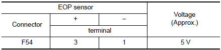
Inspection result normal?
YES >> GO TO 7.
NO >> GO TO 3.
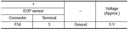
3.CHECK EOP SENSOR POWER SUPPLY-2
Check the voltage between EOP sensor harness connector and the ground.
Is inspection result normal? YES >> GO TO 5.
NO >> GO TO 4.
4.CHECK SENSOR POWER SUPPLY 2 CIRCUIT
Perform EC-484, "Diagnosis Procedure".
Is inspection result normal? YES >> Perform the trouble diagnosis for power supply circuit.
NO >> Repair or replace error-detected parts.
5.CHECK EOP SENSOR GROUND CIRCUIT
- Turn ignition switch OFF.
- Disconnect ECM harness connector.
- Check the continuity between EOP sensor harness connector and ECM harness connector.
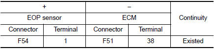
- Also check harness for short to power.
Is inspection result normal? YES >> GO TO 6.
NO >> Repair or replace error-detected parts.
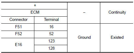
6.CHECK ECM GROUND CIRCUIT
Check the continuity between ECM harness connector and ground.
Is inspection result normal? YES >> GO TO 9.
NO >> Repair or replace error-detected parts.
7.CHECK EOP SENSOR SIGNAL CIRCUIT
- Turn ignition switch OFF.
- Disconnect ECM harness connector.
- Check the continuity between EOP sensor harness connector and ECM harness connector.
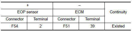
- Also check harness for short to ground and to power.
Is inspection result normal? YES >> GO TO 8.
NO >> Repair or replace error-detected parts.
8.CHECK EOP SENSOR
Refer to EC-360, "Component Inspection".
Is inspection result normal? YES >> GO TO 9.
NO >> Repair or replace error-detected parts.
9.CHECK INTERMITTENT INCIDENT
Refer to GI-41, "Intermittent Incident".
>> INSPECTION END
Component Inspection
1.CHECK EOP SENSOR
- Turn ignition switch OFF.
- Disconnect EOP sensor harness connector.
- Check resistance between EOP sensor connector terminals.
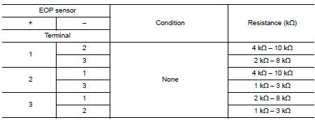
Is the inspection result normal? YES >> INSPECTION END.
NO >> Replace EOP sensor. Refer to EC-14, "Component Parts Location".
 P050A, P050B, P050E cold start control
Description
ECM controls ignition timing and engine idle speed when engine is started
with pre-warming up condition.
This control promotes the activation of three way catalyst by heating the
c ...
 P0524 engine oil pressure
DTC Description
DTC DETECTION LOGIC
DTC No.
CONSULT screen terms
(Trouble diagnosis content)
DTC detecting condition
P0524
ENGINE OIL PRESSURE
(Engine oil pressure too ...
Other materials:
Brake pedal position switch
Component Function Check
1.CHECK BRAKE PEDAL POSITION SWITCH FUNCTION
With CONSULT
Turn ignition switch ON.
Select “BRAKE SW1” in “DATA MONITOR” mode with CONSULT.
Check “BRAKE SW1” indication as per the following conditions.
Without CONSULT
...
Precaution
Precaution for Supplemental Restraint System (SRS) "AIR BAG" and "SEAT
BELT
PRE-TENSIONER"
The Supplemental Restraint System such as “AIR BAG” and “SEAT BELT
PRE-TENSIONER”, used along
with a front seat belt, helps to reduce the risk or severity of injury to the
...
Combination meter
Reference Value
VALUES ON THE DIAGNOSIS TOOL
*: DDS (hill descent control)
NOTE:
Some items are not available according to vehicle specification.
TERMINAL LAYOUT
PHYSICAL VALUES
Fail-safe
The combination meter activates the fail-safe control if the CAN
communica ...