Nissan Rogue Service Manual: P2135 TP sensor
DTC Description
DTC DETECTION LOGIC
| DTC No. | CONSULT screen terms (Trouble diagnosis content) | DTC detecting condition |
| P2135 | TP SENSOR-B1 (Throttle/pedal position sensor/switch ″A″ / ″B″ voltage correlation) | Rationally incorrect voltage is sent to ECM compared with the signals from TP sensor 1 and TP sensor |
POSSIBLE CAUSE
- Harness or connectors (TP sensor 1 or 2 circuit is open or shorted.)
- Electric throttle control actuator (TP sensor 1 or 2)
FAIL-SAFE
- The ECM controls the electric throttle control actuator in regulating the throttle opening in order for the idle position to be within +10 degrees.
- The ECM regulates the opening speed of the throttle valve to be slower than the normal condition. So, the acceleration will be poor
DTC CONFIRMATION PROCEDURE
1.CHECK DTC PRIORITY
If DTC P2135 is displayed with DTC P0643, first perform the trouble diagnosis for DTC P0643.
Is applicable DTC detected? YES >> Perform diagnosis of applicable. Refer to EC-379, "DTC Description".
NO >> GO TO 2.
2.PRECONDITIONING
If DTC Confirmation Procedure has been previously conducted, always perform the following procedure before conducting the next test.
- Turn ignition switch OFF and wait at least 10 seconds.
- Turn ignition switch ON.
- Turn ignition switch OFF and wait at least 10 seconds.
TESTING CONDITION: Before performing the following procedure, confirm that battery voltage is more than 8 V at idle.
>> GO TO 3.
3.PERFORM DTC CONFIRMATION PROCEDURE
- Start engine and let it idle for 1 second.
- Check DTC.
Is DTC detected? YES >> Proceed to EC-446, "Diagnosis Procedure".
NO >> INSPECTION END
Diagnosis Procedure
1.CHECK DTC PRIORITY
If DTC P2135 is displayed with DTC P0643, first perform the trouble diagnosis for DTC P0643.
Is applicable DTC detected? YES >> Perform diagnosis of applicable. Refer to EC-379, "DTC Description".
NO >> GO TO 2.
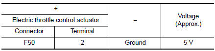
2.CHECK THROTTLE POSITION SENSOR POWER SUPPLY
- Turn ignition switch OFF.
- Disconnect electric throttle control actuator harness connector.
- Turn ignition switch ON.
- Check the voltage between electric throttle control actuator harness connector and ground.
Is the inspection result normal? YES >> GO TO 4.
NO >> GO TO 3.
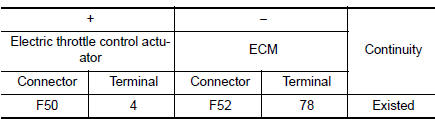
3.CHECK THROTTLE POSITION SENSOR POWER SUPPLY CIRCUIT
- Turn ignition switch OFF.
- Disconnect ECM harness connector.
- Check the continuity between electric throttle control actuator harness connector and ground.
- Also check harness for short to ground.
Is the inspection result normal? YES >> Perform the trouble diagnosis for power supply circuit.
NO >> Repair or replace error-detected parts.
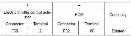
4.CHECK THROTTLE POSITION SENSOR GROUND CIRCUIT
- Turn ignition switch OFF.
- Disconnect ECM harness connector.
- Check the continuity between electric throttle control actuator harness connector and ECM harness connector.
- Also check harness for short to power.
Is the inspection result normal? YES >> GO TO 5.
NO >> Repair or replace error-detected parts.
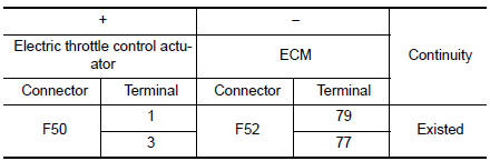
5.CHECK THROTTLE POSITION SENSOR INPUT SIGNAL CIRCUIT
- Check the continuity between electric throttle control actuator harness connector and ECM harness connector.
- Also check harness for short to ground and to power.
Is the inspection result normal? YES >> GO TO 6.
NO >> Repair open circuit or short to ground or short to power in harness or connectors.
6.CHECK THROTTLE POSITION SENSOR
Check the throttle position sensor. Refer to EC-448, "Component Inspection".
Is the inspection result normal? YES >> GO TO 7.
NO >> Replace electric throttle control actuator. Refer to EM-26, "Removal and Installation".
7.CHECK INTERMITTENT INCIDENT
Refer to GI-41, "Intermittent Incident".
>> INSPECTION END
Component Inspection
1.CHECK THROTTLE POSITION SENSOR
- Turn ignition switch OFF.
- Reconnect all harness connectors disconnected.
- Perform “ Throttle Valve Closed Position Learning”. Refer to EC-140, "Work Procedure".
- Turn ignition switch ON.
- Set selector lever to D position.
- Check the voltage between ECM harness connector terminals as per the following condition
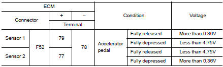
Is the inspection result normal? YES >> INSPECTION END
NO >> Replace electric throttle control actuator. Refer to EM-26, "Removal and Installation".
 P2127, P2128 APP sensor
DTC Description
DTC DETECTION LOGIC
DTC No.
CONSULT screen terms
(Trouble diagnosis content)
DTC detecting condition
P2127
APP SEN 2/CIRC
(Throttle/pedal position sens ...
 P2138 APP sensor
DTC Description
DTC DETECTION LOGIC
DTC No.
CONSULT screen terms
(Trouble diagnosis content)
DTC detecting condition
P2138
APP SENSOR
(Throttle/pedal position sensor/s ...
Other materials:
Filament
Inspection and Repair
INSPECTION
When measuring voltage, wrap tin foil around the top of the
negative
probe. Then press the foil against the wire with your finger.
Attach probe circuit tester (in Volt range) to middle portion of
each filament.
If a filament is b ...
Meter buzzer circuit
Description
The buzzer for the warning chime system is installed in the combination
meter.
The combination meter sounds the buzzer based on the signals transmitted
from various units.
Component Function Check
1. CHECK OPERATION OF METER BUZZER
Select "BUZZER" of & ...
Unit disassembly and assembly
REAR DRIVE SHAFT
Exploded View
DISASSEMBLY
Circular clip
Dust shield
Slide joint housing
Snap ring
Spider assembly
Boot band
Boot
Shaft
Circular clip
Joint sub-assembly
Sensor rotor
: Wheel side
Disassembly and Assembly
DISASSEMBLY
Final Dri ...