Nissan Rogue Service Manual: Power supply and ground circuit
COMBINATION METER
COMBINATION METER : Diagnosis Procedure
Regarding Wiring Diagram information, refer to MWI-32, "Wiring Diagram".
1.CHECK FUSES
Check that the following fuses are not blown.
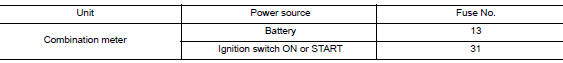
Is the fuse blown? YES >> Replace the blown fuse after repairing the affected circuit.
NO >> GO TO 2.
2.POWER SUPPLY CIRCUIT CHECK
1. Disconnect combination meter connector.
2. Check voltage between combination meter harness connector M77 terminals 45, 46 and ground.
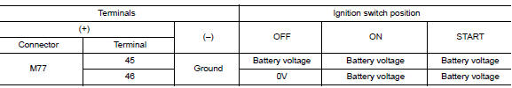
Is the inspection result normal? YES >> GO TO 3.
NO >> Repair or replace harness or connector.
3.GROUND CIRCUIT CHECK
- Turn ignition switch OFF.
- Check continuity between combination meter harness connector and ground.
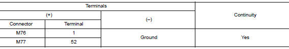
Is the inspection result normal? YES >> Inspection End.
NO >> Repair or replace harness or connector.
BCM (BODY CONTROL SYSTEM) (WITH INTELLIGENT KEY SYSTEM)
BCM (BODY CONTROL SYSTEM) (WITH INTELLIGENT KEY SYSTEM) : Diagnosis Procedure
Regarding Wiring Diagram information, refer to BCS-50, "Wiring Diagram".
1. CHECK FUSE
Check that the following fuse is not blown.

Is the fuse blown? YES >> Replace the blown fuse after repairing the affected circuit.
NO >> GO TO 2.
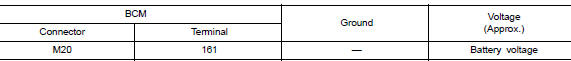
2. CHECK POWER SUPPLY CIRCUIT
- Disconnect BCM connector M20.
- Check voltage between BCM connector M20 and ground.

Is the inspection result normal? YES >> GO TO 3.
NO >> Repair or replace harness or connectors.
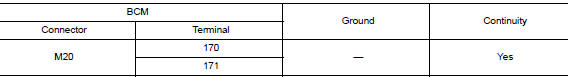
3. CHECK GROUND CIRCUIT
Check continuity between BCM connector M20 and ground.
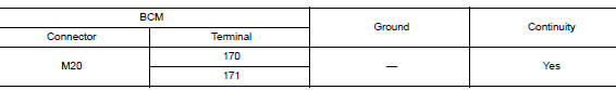
Is the inspection result normal? YES >> Inspection End.
NO >> Repair or replace harness or connectors.
BCM (BODY CONTROL SYSTEM) (WITHOUT INTELLIGENT KEY SYSTEM)
BCM (BODY CONTROL SYSTEM) (WITHOUT INTELLIGENT KEY SYSTEM) : Diagnosis Procedure
Regarding Wiring Diagram information, refer to BCS-110, "Wiring Diagram".
1. CHECK FUSE
Check that the following fuse is not blown.

Is the fuse blown? YES >> Replace the blown fuse after repairing the affected circuit.
NO >> GO TO 2.
2. CHECK POWER SUPPLY CIRCUIT
- Disconnect BCM connector M20.
- Check voltage between BCM connector M20 and ground.
Is the inspection result normal? YES >> GO TO 3.
NO >> Repair or replace harness or connectors.
3. CHECK GROUND CIRCUIT
Check continuity between BCM connector M20 and ground.
Is the inspection result normal? YES >> Inspection End.
NO >> Repair or replace harness or connectors.

 Meter buzzer circuit
Description
The buzzer for the warning chime system is installed in the combination
meter.
The combination meter sounds the buzzer based on the signals transmitted
from various units.
C ...
Other materials:
Liquid Gasket
REMOVAL OF LIQUID GASKET SEALING
After removing the bolts and nuts, separate the mating surface and
remove the liquid gasket using Tool (A).
Tool Number : KV10111100 (J-37228)
CAUTION:
Be careful not to damage the mating surfaces.
In areas where the cutter is difficult to use, u ...
P1078 EVT control position sensor
DTC Description
DTC DETECTION LOGIC
DTC No.
CONSULT screen terms
(Trouble diagnosis content)
DTC detecting condition
P1078
EXH TIM SEN/CIRC-B1
(EXH TIM SEN/CIRC-B1)
An excessively high or low voltage from the sensor is sent to ECM.
POSSIBLE CAUSE
H ...
Preparation
Special Service Tool
The actual shape of the tools may differ from those illustrated here.
Tool number
(TechMate No.)
Tool name
Description
—
(J-46534)
Trim Tool Set
Removing trim components
Commercial Service Tools
Tool name
...