Nissan Rogue Service Manual: Removal and installation
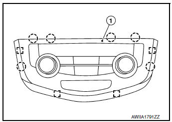
FRONT AIR CONTROL
Removal and Installation
REMOVAL
- Release the front air control clips and pawls using a suitable tool.
 : Metal clip
 : Pawl
- Disconnect the harness connector from the front air control (1) and remove.
INSTALLATION
Installation is in the reverse order of removal.
INTAKE SENSOR
Exploded View
- Intake sensor
- Heating and cooling unit assembly
Removal and Installation
REMOVAL
- Remove front foot duct (LH). Refer to VTL-10, "FRONT FOOT DUCT : Removal and Installation".
- Disconnect the harness connector and remove intake sensor.
INSTALLATION
Installation is in the reverse order of removal.
REFRIGERANT PRESSURE SENSOR
Removal and Installation
REMOVAL
- Discharge the refrigerant. Refer to HA-23, "Recycle Refrigerant".
- Remove front bumper fascia. Refer to EXT-17, "Removal and Installation".
- Disconnect the harness connector from the refrigerant pressure sensor.
- Remove the refrigerant pressure sensor (1) from the condenser.
 : Front
CAUTION: Cap or wrap the opening of the refrigerant pressure sensor with suitable material such as vinyl tape to avoid the entry of air.
INSTALLATION
Installation is in the reverse order of removal.
CAUTION:
- Do not reuse O-ring.
- Apply A/C oil to new O-ring for installation.
- After charging refrigerant, check for leaks. Refer to HA-21, "Leak Test".
DOOR MOTOR
Component Parts Location
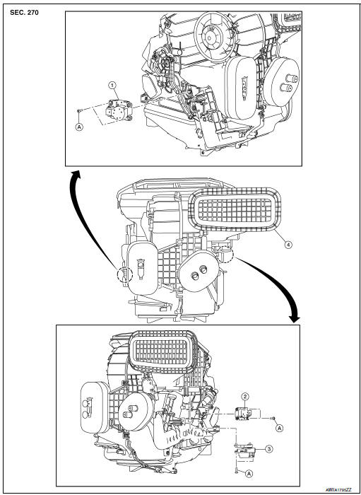
- Mode door motor
- Air mix door motor
- Intake door motor
- Heating and cooling unit assembly
- Screw
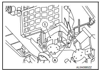
INTAKE DOOR MOTOR
INTAKE DOOR MOTOR : Removal and Installation
REMOVAL
- Remove front foot duct (LH). Refer to VTL-10, "FRONT FOOT DUCT : Removal and Installation".
- Disconnect the harness connector from the intake door motor.
- Remove screws (A) and intake door motor (1).
INSTALLATION
Installation is in the reverse order of removal.
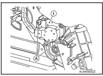
MODE DOOR MOTOR
MODE DOOR MOTOR : Removal and Installation
REMOVAL
- Remove front foot duct (RH). Refer to VTL-10, "FRONT FOOT DUCT : Removal and Installation".
- Disconnect the harness connector from the mode door motor.
- Remove screws (A) and mode door motor (1).
INSTALLATION
Installation is in the reverse order of removal.
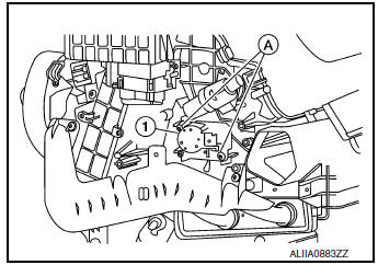
AIR MIX DOOR MOTOR
AIR MIX DOOR MOTOR : Removal and Installation
REMOVAL
- Remove front foot duct (LH). Refer to VTL-10, "FRONT FOOT DUCT : Removal and Installation".
- Disconnect the harness connector from the air mix door motor.
- Remove screws (A) and air mix door motor (1).
INSTALLATION
Installation is in the reverse order of removal.
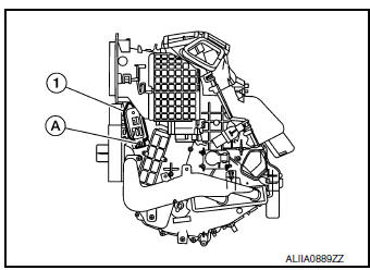
VARIABLE BLOWER CONTROL
Removal and Installation
REMOVAL
- Remove center console side finisher (LH). Refer to IP-18, "Exploded View"
- Disconnect the harness connector from the variable blower control.
- Remove screw (A) and variable blower control (1).
INSTALLATION
Installation is in the reverse order of removal.
 Symptom diagnosis
HEATER AND AIR CONDITIONING SYSTEM CONTROL SYMPTOMS
Symptom Table
SYMPTOM TABLE
Symptom
Reference Page
A/C system does not come on.
Go to Trouble Diagnosis Procedure f ...
 Body interior
...
Other materials:
Power supply routing circuit
Wiring Diagram —Battery Power Supply —
Wiring Diagram —Accessory Power Supply —
Wiring Diagram —Ignition Power Supply —
Fuse
If fuse is blown, be sure to eliminate cause of malfunction before
ins ...
Preparation
Special Service Tool
The actual shapes of the tools may differ from those illustrated here.
Tool number
(TechMate No.)
Tool name
Description
—
(J-39570)
Chassis Ear
Locating the noise
—
(J-50397)
NISSAN Squeak and Rattle Kit
...
Combination meter
Removal and Installation
REMOVAL
Disconnect the negative battery terminal. Refer to PG-77, "Removal
and Installation".
Remove the cluster lid A. Refer to IP-20, "Removal and
Installation".
Remove screws (A), from the combination meter (1).
...