Nissan Rogue Service Manual: Steering switch
Description
When one of the steering switches is pushed, the resistance in the steering switch changes the signal to identify which button is controlling the information display.
Diagnosis Procedure
Regarding Wiring Diagram information, refer to MWI-32, "Wiring Diagram".
1.CHECK STEERING SWITCH CIRCUIT
- Turn ignition switch OFF.
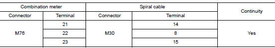
- Disconnect combination meter harness connector M76 and spiral cable harness connector M30.
- Check continuity between combination meter harness connector M76 and spiral cable harness connector M30.
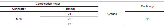
- Check continuity between combination meter harness connector M76 and ground.
Is the inspection result normal? YES >> Inspection End.
NO >> Repair or replace harness or connector.
Component Inspection
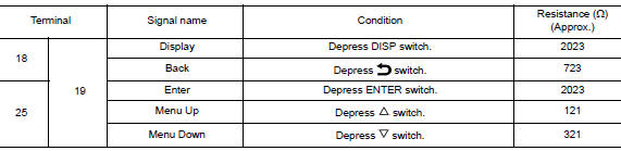
1.CHECK STEERING SWITCH RESISTANCE
Check resistance between the following steering switch terminals.
Is the inspection result normal? YES >> GO TO 2.
NO >> Replace steering wheel switch. Refer to AV-65, "Removal and Installation".
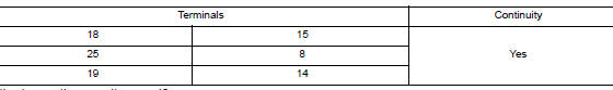
2.CHECK SPIRAL CABLE
Check continuity between the following spiral cable terminals.
Is the inspection result normal? YES >> Inspection End.
NO >> Replace spiral cable. Refer to SR-15, "Removal and Installation".
 Meter control switch signal circuit
Diagnosis Procedure
Regarding Wiring Diagram information, refer to MWI-32, "Wiring Diagram".
1.CHECK METER CONTROL SWITCH SIGNAL
Turn ignition switch ON.
Check voltage be ...
 Washer level switch signal circuit
Description
Transmits the washer fluid level switch signal to the combination meter.
Diagnosis Procedure
Regarding Wiring Diagram information, refer to MWI-32, "Wiring Diagram".
1.CHECK ...
Other materials:
Diagnosis system (ECM)
DIAGNOSIS DESCRIPTION
DIAGNOSIS DESCRIPTION : 1st Trip Detection Logic and Two Trip Detection
Logic
When a malfunction is detected for the first time, 1st trip DTC and 1st trip
Freeze Frame data are stored in the
ECM memory. The MIL will not illuminate at this stage. <1st trip>
If the ...
Precaution
Precaution for Supplemental Restraint System (SRS) "AIR BAG" and "SEAT
BELT
PRE-TENSIONER"
The Supplemental Restraint System such as “AIR BAG” and “SEAT BELT PRE-TENSIONER”,
used along
with a front seat belt, helps to reduce the risk or severity of injury to the
...
DTC/Circuit diagnosis
C1201 AWD CONTROL UNIT
DTC Description
DTC DETECTION LOGIC
DTC No.
CONSULT screen terms
(Trouble diagnosis content)
DTC detecting condition
C1201
CONTROLLER FAILURE
(Control unit failure)
Malfunction has occurred inside AWD control unit.
POSSIBLE CAUSE
Int ...