Nissan Rogue Service Manual: Symptom diagnosis
EXTERIOR LIGHTING SYSTEM SYMPTOMS
Symptom Table
CAUTION: Perform the self-diagnosis with CONSULT before the symptom diagnosis. Perform the trouble diagnosis if any DTC is detected.
NORMAL OPERATING CONDITION
Description
AUTO LIGHT SYSTEM
The headlamp may not be turned ON/OFF immediately after passing dark area or bright area (short tunnel, sky bridge, shadowed area, etc.) while using the auto light system. This is caused by for the control difference.
This is normal.
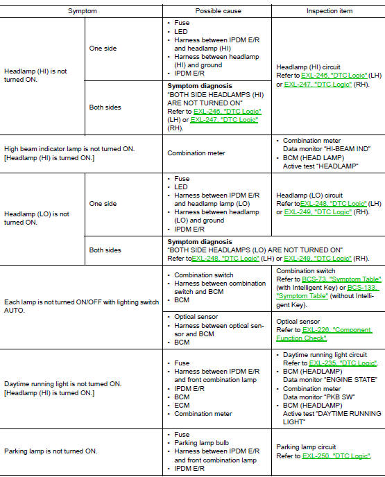
BOTH SIDE HEADLAMPS (HI) ARE NOT TURNED ON
Description
Both side headlamps (HI) are not turned ON when setting to the lighting switch HI or PASS.
Diagnosis Procedure
1.COMBINATION SWITCH INSPECTION
Check combination switch. Refer to BCS-73, "Symptom Table" (with Intelligent Key system) or BCS-133, "Symptom Table" (without Intelligent Key system).
Is the inspection result normal? YES >> GO TO 2.
NO >> Repair or replace the malfunctioning part.
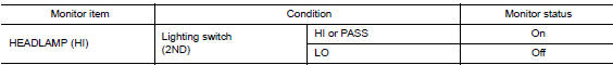
2.CHECK HEADLAMP (HI) REQUEST SIGNAL INPUT
 CONSULT DATA MONITOR
- Select “HEADLAMP (HI)”of IPDM E/R data monitor item.
- With operating the lighting switch, check the monitor status.
Is the inspection result normal? YES >> GO TO 3.
NO >> Replace BCM. Refer to BCS-75, "Removal and Installation" (with Intelligent Key system) or BCS- 135, "Removal and Installation" (without Intelligent Key system).
3.HEADLAMP (HI) CIRCUIT INSPECTION
Check headlamp (HI) circuit. Refer to EXL-246, "DTC Logic" (LH) or EXL-247, "DTC Logic" (RH).
Is the inspection result normal? YES >> Refer to GI-41, "Intermittent Incident".
NO >> Repair or replace the malfunctioning part.
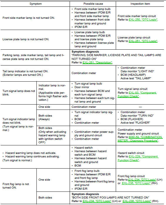
BOTH SIDE HEADLAMPS (LO) ARE NOT TURNED ON
Description
Both side headlamps (LO) are not turned ON in any condition.
Diagnosis Procedure
1.CHECK COMBINATION SWITCH
Check combination switch. Refer to BCS-73, "Symptom Table" (with Intelligent Key system) or BCS-133, "Symptom Table" ( without Intelligent Key system).
Is the inspection result normal? YES >> GO TO 2.
NO >> Repair or replace the malfunctioning part.
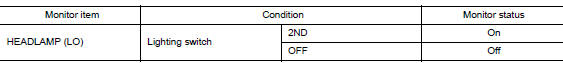
2.CHECK HEADLAMP (LO) REQUEST SIGNAL INPUT
CONSULT DATA MONITOR
- Select “HEADLAMP (LO)”of IPDM E/R data monitor item.
- With operating the lighting switch, check the monitor status.
Is the inspection result normal? YES >> GO TO 3.
NO >> Replace BCM. Refer to BCS-75, "Removal and Installation" (with Intelligent Key system) or BCS- 135, "Removal and Installation" (without Intelligent Key system).
3.HEADLAMP (LO) CIRCUIT INSPECTION
Check headlamp (LO) circuit. Refer to EXL-248, "DTC Logic" (LH) or EXL-249, "DTC Logic" (RH).
Is the inspection result normal? YES >> Refer to GI-41, "Intermittent Incident".
NO >> Repair or replace the malfunctioning part.
PARKING, LICENSE PLATE, SIDE MARKER AND TAIL LAMPS ARE NOT TURNED ON
Description
The parking, license plate, side marker, tail lamps and each illumination are not turned ON in any condition.
Diagnosis Procedure
1.COMBINATION SWITCH INSPECTION
Check combination switch. Refer to BCS-73, "Symptom Table" (with Intelligent Key system) or BCS-133, "Symptom Table" (without Intelligent Key system).
Is the combination switch normal? YES >> GO TO 2.
NO >> Repair or replace the malfunctioning part.
2.CHECK TAIL LAMP REQUEST SIGNAL INPUT
CONSULT DATA MONITOR
- Select “TAIL LAMP” of IPDM E/R data monitor item.
- With operating the lighting switch, check the monitor status.
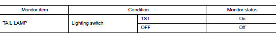
Is the inspection result normal? YES >> Replace IPDM E/R. Refer to PCS-35, "Removal and Installation".
NO >> Replace BCM. Refer to BCS-75, "Removal and Installation" (with Intelligent Key system) or BCS- 135, "Removal and Installation" (without Intelligent Key system).
BOTH SIDE FRONT FOG LAMPS ARE NOT TURNED ON
Description
The front fog lamps are not turned ON in any condition.
Diagnosis Procedure
1.CHECK COMBINATION SWITCH
Check combination switch. Refer to BCS-73, "Symptom Table" (with Intelligent Key) or BCS-133, "Symptom Table" (without Intelligent Key).
Is the inspection result normal? YES >> GO TO 3.
NO >> Repair or replace the malfunctioning part.
2.CHECK FRONT FOG LAMP REQUEST SIGNAL INPUT
CONSULT DATA MONITOR
- Select “FRONT FOG LAMP REQ” of IPDM E/R data monitor item.
- With operating the front fog lamp switch, check the monitor status.
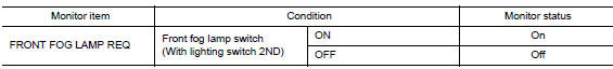
Is the item status normal? YES >> Replace IPDM E/R. Refer to PCS-35, "Removal and Installation".
NO >> Replace BCM. Refer to BCS-75, "Removal and Installation" (with Intelligent Key) or BCS-135, "Removal and Installation" (without Intelligent Key).
 DTC/circuit diagnosis
POWER SUPPLY AND GROUND CIRCUIT
BCM (BODY CONTROL SYSTEM) (WITH INTELLIGENT KEY SYSTEM)
BCM (BODY CONTROL SYSTEM) (WITH INTELLIGENT KEY SYSTEM) : Diagnosis
Procedure
Regarding Wiring Diagram infor ...
 Periodic maintenance
HEADLAMP AIMING ADJUSTMENT
Inspection
PREPARATION BEFORE ADJUSTING
Before performing aiming adjustment, check the following:
Make sure all tires are inflated to correct pressure.
...
Other materials:
Wiring diagram
POWER DISTRIBUTION SYSTEM
Wiring Diagram
...
C1601 battery power supply
DTC Logic
DTC DETECTION LOGIC
DTC
Display item
Malfunction detected condition
Possible cause
C1601
BATTERY VOLT
When a power supply voltage to the EPS control unit
is maintained at 18.2 V or more or at less than 9 V
continuously for five second ...
Monitor, climate, audio, phone and voice recognition systems
WARNING
Positioning of the heating or air conditioning
controls and display controls
should not be done while driving in order
that full attention may be given to
the driving operation.
Do not disassemble or modify this system.
If you do, it may result ...