Nissan Rogue Service Manual: Brake booster
Exploded View
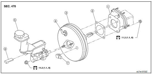
- Spacer
- Gasket
- Brake booster
- Check valve
- Reservoir tank
- Brake fluid level sensor
- Brake booster pressure sensor
Removal and installation
REMOVAL
- Remove the cowl top. Refer to EXT-25, "Removal and Installation".
- Remove the instrument lower panel LH. Refer to IP-22, "Removal and Installation".
- Remove the knee protector. Refer to IP-14, "Exploded View".
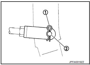
- Remove the snap pin (1) and clevis pin (2) from the brake pedal.
- Disconnect vacuum hose from brake booster. Refer to BR-32, "Exploded View".
- Remove master cylinder assembly. Refer to BR-27, "Removal and Installation".
- Disconnect the harness connector from the brake booster pressure sensor.
- Remove the brake booster pressure sensor.
- Remove the nuts on the brake booster and brake pedal.
CAUTION: Secure the brake booster to avoid damage to components.
- Remove the brake booster.
CAUTION: Do not deform or bend the brake pipes.
INSTALLATION
- Install a new gasket between the brake booster and dash panel.
CAUTION: Do not reuse the gasket.
- Install the brake booster to the dash panel from the engine room
side.
CAUTION: Do not damage brake booster stud bolt threads during installation.
- Install the nuts to the brake booster and brake pedal. Refer to BR-30, "Exploded View".
- Install the brake booster pressure sensor.
- Connect the harness connector to the brake booster pressure sensor.
- Install master cylinder assembly. Refer to BR-27, "Removal and Installation".
- Connect vacuum hose to brake booster. Refer toBR-32, "Exploded View".
- Install the clevis pin and snap pin to the brake pedal.
- Adjust the brake pedal. Refer to BR-15, "Adjustment".
- Install the knee protector. Refer to IP-14, "Exploded View".
- Install instrument lower panel LH. Refer to IP-22, "Removal and Installation".
- Bleed the brake system. Refer to BR-16, "Bleeding Brake System".
- Inspect the brake booster. Refer to BR-10, "Inspection".
 Brake master cylinder
Exploded View
Reservoir cap
Oil strainer
Reservoir tank
Brake fluid level sensor
Cylinder body
Pin
O-ring
Grommet
: Apply PBC (Poly Butyl
Cuprysil) grease or sil ...
 Vacuum lines
Exploded View
Clamp
Vacuum hose
Vacuum tube
Clip
Vacuum hose
To intake manifold
To brake booster
Paint mark
Stamp indicating engine direction
Removal an ...
Other materials:
FM/AM radio with compact disc (CD) player
(if so equipped)
FM/AM radio with compact disc (CD) player
CD eject button
CD button
Display screen
CD insert slot
SEEK button
SCAN button
TRACK button
BACK button
iPod MENU button
TUNE/FOLDER knob, ENTER/SETTING
button
Sta ...
Operating range
Operating range
The Intelligent Key functions can only be used
when the Intelligent Key is within the specified
operating range.
When the Intelligent Key battery is almost discharged
or strong radio waves are present near
the operating location, the Intelligent Key system’s
operating ...
Timing chain
Exploded View
Cylinder block
Timing chain slack guide
Chain tensioner
Timing chain
Camshaft sprocket (EXH)
Camshaft sprocket (INT)
Oil filter
Front cover
O-ring
Oil pressure sensor
Valve timing control cover O-rings
...