Nissan Rogue Service Manual: Component parts
METER SYSTEM
METER SYSTEM : Component Parts Location
 Vehicle front
- View of the fuel pump and fuel level sensor inspection hole covers with the rear seat removed.
- View of front engine assembly
|
No. |
Component |
Function |
| 1 | Combination meter | Refer to MWI-8, "METER SYSTEM : System Description". |
| 2 | Steering switch | Refer to MWI-18, "Switch Name and Function". |
| 3 | Meter control switch | Refer to MWI-18, "Switch Name and Function". |
| 4 | Fuel level sensor unit (sub) | Transmits the fuel level sensor signal to the combination meter. |
| 5 | Fuel level sensor unit (main) | Transmits the fuel level sensor signal to the combination meter |
| 6 | Seat belt buckle switch LH | Transmits the seat belt buckle switch signal LH to the combination meter. |
| 7 | ABS actuator and electric unit (control unit) |
|
| 8 | Engine oil pressure sensor | Transmits the engine oil pressure sensor signal to the ECM. |
| 9 | Washer fluid level switch |
|
| 10 | Ambient sensor |
|
| 11 | ECM |
|
| 12 | TCM |
|
| 13 | BCM |
|
| 14 | Parking brake switch | Transmits the parking brake switch signal to the combination meter. |
METER SYSTEM : Design
ARRANGEMENT OF COMBINATION METER
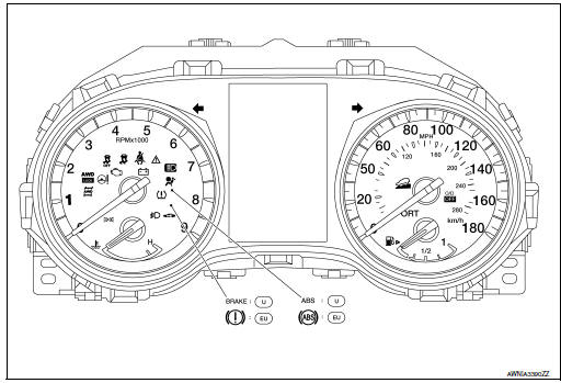
U: USA
EU: Except USA

 System
METER SYSTEM
METER SYSTEM : System Description
SYSTEM DIAGRAM
Combination Meter Input Signal (CAN Communication Signal)
DESCRIPTION
Combination Meter
The combination meter c ...
Other materials:
Key interlock cable
Exploded View
Key cylinder
Clip
Key interlock cable
Shift selector assembly
Removal and Installation
REMOVAL
CAUTION:
Always apply the parking brake before performing removal and installation.
Move shift selector to the “N” position.
Remo ...
Ignition signal
Component Function Check
1.INSPECTION START
Turn ignition switch OFF, and restart engine.
Does the engine start?
YES-1 >> With CONSULT: GO TO 2.
YES-2 >> Without CONSULT: GO TO 3.
NO >> Proceed to EC-470, "Diagnosis Procedure".
2.CHECK IGNITION SIGNAL FUNCTIO ...
Additional service when replacing TCM
Description
Always perform the following items when the TCM is replaced.
TCM PROGRAMMING
Since vehicle specifications are not yet written in a new TCM, it
is necessary to write them with CONSULT.
CAUTION:
When replacing TCM, save TCM data on CONSULT before removing TCM.
SAVING ...