Nissan Rogue Service Manual: Diagnosis and repair workflow
Work Flow
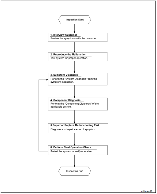
OVERALL SEQUENCE

DETAILED FLOW
1. OBTAIN INFORMATION ABOUT SYMPTOM
Interview the customer to obtain as much information as possible about the conditions and environment under which the malfunction occurred.
>> GO TO 2.
2. CONFIRM CONCERN
Check the malfunction on the vehicle that the customer describes.
Inspect the relation of the symptoms and the condition when the symptoms occur.
>> GO TO 3.
3. IDENTIFY THE MALFUNCTIONING SYSTEM WITH SYMPTOM DIAGNOSIS
Use Symptom diagnosis from the symptom inspection result in step 2 and then identify where to start performing the diagnosis based on possible causes and symptoms.
>> GO TO 4.
4. PERFORM THE COMPONENT DIAGNOSIS OF THE APPLICABLE SYSTEM
Perform the diagnosis with Component diagnosis of the applicable system.
>> GO TO 5.
5. REPAIR OR REPLACE THE MALFUNCTIONING PARTS
Repair or replace the specified malfunctioning parts.
>> GO TO 6.
6. FINAL CHECK
Check that malfunctions are not reproduced when obtaining the malfunction information from the customer, referring to the symptom inspection result in step 2.
Are the malfunctions corrected? YES >> Inspection End.
NO >> GO TO 3.
 Basic inspection
...
 Inspection and adjustment
ADDITIONAL SERVICE WHEN REPLACING CONTROL UNIT
ADDITIONAL SERVICE WHEN REPLACING CONTROL UNIT : Special Repair
Requirement
INITIALIZATION PROCEDURE
Moonroof
If the moonroof does not open or clos ...
Other materials:
Front bumper
Exploded View
Front bumper fascia side
bracket (RH)
Front bumper reinforcement
support (RH)
Front bumper reinforcement
Front energy absorber
Front lower grille
Front fog lamp (RH) (if equipped)
Front bumper fascia
Front bumper fascia finisher
(RH) (if equipped)
...
P062F EEPROM
Description
TCM compares the calculated value stored in the flash ROM with the value
stored in TCM. If the calculated
value does not agree with the stored value, TCM judges this as a malfunction.
DTC Description
TCM compares the calculated value stored in the flash ROM with the value
stored ...
P1212 TCS communication line
Description
This CAN communication line is used to control the smooth engine operation
during the TCS operation. Pulse
signals are exchanged between ECM and “ABS actuator and electric unit (control
unit)”.
Be sure to erase the malfunction information such as DTC not only for “ABS
ac ...
