Nissan Rogue Service Manual: Electrical load signal
Description
The electrical load signal (Headlamp switch signal, rear window defogger switch signal, etc.) is transferred via the CAN communication.
Component Function Check
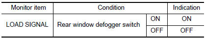
1.CHECK REAR WINDOW DEFOGGER SWITCH FUNCTION
- Turn ignition switch ON.
- Connect CONSULT and select “DATA MONITOR” mode.
- Select “LOAD SIGNAL” and check indication under the following conditions.
Is the inspection result normal? YES >> GO TO 2.
NO >> Proceed to EC-462, "Diagnosis Procedure".
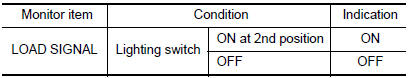
2.CHECK LIGHTING SWITCH FUNCTION
Check “LOAD SIGNAL” indication under the following conditions.
Is the inspection result normal? YES >> GO TO 3.
NO >> Proceed to EC-462, "Diagnosis Procedure".
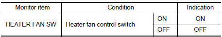
3.CHECK HEATER FAN CONTROL SWITCH FUNCTION
Select “HEATER FAN SW” and check indication under the following conditions.
Is the inspection result normal? YES >> INSPECTION END
NO >> Proceed to EC-462, "Diagnosis Procedure".
Diagnosis Procedure
1.INSPECTION START
Confirm the malfunctioning circuit (rear window defogger, headlamp or heater fan). Refer to EC-462, "Component Function Check".
Which circuit is related to the incident? Rear window defogger>>GO TO 2.
Headlamp>>GO TO 3.
Heater fan>>GO TO 4.
2.CHECK REAR WINDOW DEFOGGER SYSTEM
Check rear window defogger system. Refer to DEF-19, "Work Flow".
>> INSPECTION END
3.CHECK HEADLAMP SYSTEM
Check headlamp system. Refer to EXL-82, "Work Flow" (with halogen headlamp) or EXL-219, "Work Flow" (with LED headlamp).
>> INSPECTION END
4.CHECK HEATER FAN CONTROL SYSTEM
Check heater fan control system. Refer to HAC-46, "Work Flow" (with automatic air conditioner) or HAC-146, "Work Flow" (with manual air conditioner).
>> INSPECTION END
 Cooling fan
Component Function Check
1.CHECK COOLING FAN FUNCTION
With CONSULT
Turn ignition switch ON.
Perform “COOLING FAN (DUAL)” in “ACTIVE TEST” mode of “IPDM E/R”
using CO ...
 Fuel injector
Component Function Check
1.INSPECTION START
Turn ignition switch to START.
Are any cylinders ignited?
YES >> GO TO 2.
NO >> Proceed to EC-464, "Diagnosis Procedure".
2. ...
Other materials:
Component parts
CVT CONTROL SYSTEM
CVT CONTROL SYSTEM : Component Parts Location
Engine room, LH
Transaxle assembly
No.
Component
Function
1
Combination meter
Mainly transmits the following signal to TCM via CAN communication.
Overdrive control switch signal
...
Output speed sensor
Exploded View
Transaxle assembly
Output speed sensor
O-ring
Always replace after every
disassembly.
: N·m (kg-m, in-lb)
: Apply CVT fluid
Removal and Installation
REMOVAL
Remove engine undercover. Refer to TM-209, "Removal and
Installation".
Di ...
Outside mirrors
Outside mirrors
The outside mirror remote control will operate
only when the ignition switch is in the ACC or ON
position.
Move the small switch 1 to select the right or left
mirror. Adjust each mirror to the desired position
using the large switch 2 .
WARNING
Objects v ...