Nissan Rogue Service Manual: Heating and cooling unit assembly
Exploded View
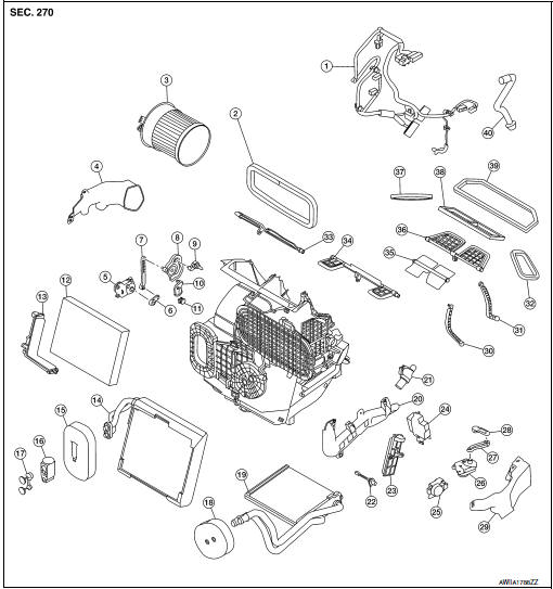
Steering Member
- Heating and cooling unit assembly
- Steering member
- Bolt
- Nut
Automatic Air Conditioning
- Wiring harness
- Air mix door duct (LH)
- Air mix door duct (RH)
- Intake housing gasket
- Blower motor
- Front foot duct (RH)
- Mode door motor
- Mode door motor link
- Mode door motor link 2
- Mode door motor main link
- Rear foot door lever
- Front foot door link
- Front foot door lever
- Air mix door motor (RH)
- Air mix door motor link (RH)
- Air mix door motor link 2 (RH)
- Air mix door lever (RH)
- In-cabin microfilter
- In-cabin microfilter cover
- Evaporator
- Evaporator grommet
- Expansion valve
- Expansion valve plug
- Heater core
- Heater core grommet
- Heater core pipe cover
- Aspirator
- Intake sensor
- Inspection cover
- Variable blower control
- Air mix door motor (LH)
- Front foot duct (LH)
- Intake door motor
- Intake door motor link
- Intake door lever
- Internal door linkage 1
- Internal door linkage 2
- Side ventilator duct gasket (LH)
- Rear foot door
- Front foot door
- Center ventilator door
- Defroster door
- Side ventilator duct gasket (RH)
- Center ventilator duct gasket
- Defroster duct gasket
- Drain hose
Manual Air Conditioning
- Wiring harness
- Intake housing gasket
- Blower motor
- Front foot duct
- Mode door motor
- Mode door motor link
- Mode door motor link 2
- Mode door motor main link
- Rear foot door lever
- Front foot door link
- Front foot door lever
- In-cabin microfilter
- In-cabin microfilter cover
- Evaporator
- Evaporator grommet
- Expansion valve
- Expansion valve plug
- Heater core grommet
- Heater core
- Heater core pipe cover
- Aspirator
- Intake sensor
- Inspection cover
- Variable blower control
- Air mix door motor
- Intake door motor
- Intake door motor link
- Intake door lever
- Front foot duct (LH)
- Internal door linkage 1
- Internal door linkage 2
- Side ventilator duct gasket (LH)
- Rear foot door
- Front foot door
- Center ventilator door
- Defroster door
- Side ventilator duct gasket (RH)
- Center ventilator duct gasket
- Defroster duct gasket
- Drain hose
HEATING AND COOLING UNIT ASSEMBLY
HEATING AND COOLING UNIT ASSEMBLY : Removal and Installation
REMOVAL
CAUTION: Before servicing, turn the ignition switch off, disconnect both battery cables and wait at least three minutes.
NOTE: When removing components such as hoses, lines/tubes, etc., cap or plug openings to prevent fluid from leaking.
- Disconnect the negative and positive battery terminals and wait at least three minutes. Refer to PG-75, "Removal and Installation (Battery)".
- Discharge the refrigerant. Refer to HA-23, "Recycle Refrigerant".
- Drain the engine coolant. Refer to CO-8, "Draining".
- Remove instrument panel assembly. Refer to IP-14, "INSTRUMENT PANEL ASSEMBLY : Removal and Installation".
- Remove steering column. Refer to ST-12, "Removal and Installation".
- Remove dash side finishers (LH/RH). Refer to INT-24, "DASH SIDE FINISHER : Removal and Installation".
- Remove front floor connecting ducts (LH/RH). Refer to VTL-10, "FRONT FLOOR DUCT : Removal and Installation - Front Floor Connecting Duct".
- Remove the cowl top extension. Refer to EXT-25, "Removal and Installation".
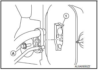
- Remove the bolt (A) that retains the low-pressure pipe and highpressure pipe to the expansion valve (1).
CAUTION: Cap or wrap the joint of the pipe with suitable material such as vinyl tape to avoid the entry of air.
- Disconnect the heater hoses from the heater core.
- Remove the nuts and bolts that retain the steering member to the vehicle body.
- Disconnect the drain hose from the heating and cooling unit assembly.
- Disconnect the harness connectors from the heating and cooling unit assembly and steering member.
- Remove the heating and cooling unit assembly and steering member
from the vehicle as an assembly.
CAUTION: Use care not to damage the seats when removing the steering member.
- Remove the bolts that retain the heating and cooling unit assembly to the steering member.
- Separate the heating and cooling unit assembly from the steering member.
INSTALLATION
Installation is in the reverse order of removal.
CAUTION:
- Do not reuse O-rings.
- Apply A/C oil to new O-rings for installation.
- After charging refrigerant, check for leaks. Refer to HA-21, "Leak Test".
HEATER CORE
HEATER CORE : Exploded View
- Heating and cooling unit assembly
- Heater core
- Heater core grommet
- Heater core pipe cover
 Front
Front
HEATER CORE : Removal and Installation
REMOVAL
NOTE: When removing components such as hoses, lines/tubes, etc., cap or plug openings to prevent fluid from spilling.
- Discharge the refrigerant. Refer to HA-23, "Recycle Refrigerant".
- Drain the engine coolant. Refer to CO-8, "Draining".
- Remove heating and cooling unit assembly. Refer to HA-42, "HEATING AND COOLING UNIT ASSEMBLY : Removal and Installation".
- Remove front foot duct (LH). Refer to VTL-10, "FRONT FOOT DUCT : Removal and Installation".
- Remove screws and heater core pipe cover. Refer to HA-39, "Exploded View".
- Remove heater core.
INSTALLATION
Installation is in the reverse order of removal.
EVAPORATOR
EVAPORATOR : Exploded View
- Evaporator
- Expansion valve
- Heating and cooling unit assembly
EVAPORATOR : Removal and Installation
REMOVAL
- Discharge the refrigerant. Refer to HA-23, "Recycle Refrigerant".
- Remove front foot duct (LH). Refer to VTL-10, "FRONT FOOT DUCT : Removal and Installation".
- Remove heater core. Refer to HA-43, "HEATER CORE : Removal and Installation".
- Remove intake door motor. Refer to HAC-110, "INTAKE DOOR MOTOR : Removal and Installation" (AUTOMATIC AIR CONDITIONING) or HAC-185, "INTAKE DOOR MOTOR : Removal and Installation" (MANUAL AIR CONDITIONING).
- Remove air mix door motor (LH) (AUTOMATIC AIR CONDITONING). Refer to HAC-110, "AIR MIX DOOR MOTOR : Removal and Installation".
- Remove air mix door motor (MANUAL AIR CONDITIONING). Refer to HAC-185, "AIR MIX DOOR MOTOR : Removal and Installation".
- Separate the heating and cooling unit assembly and remove evaporator.
INSTALLATION
Installation is in the reverse order of removal.
CAUTION:
- Do not reuse O-rings.
- Apply A/C oil to new O-rings for installation.
- After charging the refrigerant, check for leaks. Refer to HA-21, "Leak Test"
EXPANSION VALVE
EXPANSION VALVE : Removal and Installation
REMOVAL
- Discharge the refrigerant. Refer to HA-23, "Recycle Refrigerant".
- Remove cowl top extension. Refer to EXT-25, "Removal and Installation".
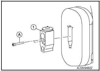
- Remove the bolt (A) that retains the low-pressure pipe and highpressure
pipe to the expansion valve (1).
CAUTION: Cap or wrap the joint of the pipe with suitable material such as vinyl tape to avoid the entry of air.
- Remove bolts (A) and expansion valve (1).
INSTALLATION
Installation is in the reverse order of removal.
CAUTION:
- Tighten bolts to specification. Refer to HA-32, "Exploded View".
- Do not reuse O-rings.
- Apply A/C oil to new O-rings for installation.
- After charging refrigerant, check for leaks. Refer to HA-21, "Leak Test".
 Condenser
Exploded View
Air guide (LH)
Condenser upper bracket (LH)
Condenser (includes liquid tank)
Condenser upper bracket (RH)
Air guide (RH)
Refrigerant pressure sensor
C ...
 Service data and specifications (SDS)
Compressor
Oil
Refrigerant
...
Other materials:
Removal and installation
NATS ANTENNA AMP.
Exploded View
Instrument finisher B
Push button ignition switch
NATS antenna amp.
Pawl
Removal and Installation
REMOVAL
Remove the instrument finisher B. Refer to IP-16, "INSTRUMENT
FINISHER B : Removal and Installation".
Release ...
Unit removal and installationEMBER
REAR SUSPENSION M
Exploded View
Rear suspension member
Suspension member stay
(RH)
Suspension member stay (LH)
Bound bumper
Front
Removal and Installation - FWD
REMOVAL
Remove wheel and tires using power tool. Refer to WT-60, "Exploded
Vie ...
Precaution
Precaution for Supplemental Restraint System (SRS) "AIR BAG" and "SEAT
BELT
PRE-TENSIONER"
The Supplemental Restraint System such as “AIR BAG” and “SEAT BELT PRE-TENSIONER”,
used along
with a front seat belt, helps to reduce the risk or severity of injury to the
...