Nissan Rogue Service Manual: Condenser
Exploded View
- Air guide (LH)
- Condenser upper bracket (LH)
- Condenser (includes liquid tank)
- Condenser upper bracket (RH)
- Air guide (RH)
- Refrigerant pressure sensor
- Condenser lower bracket (RH)
- Condenser lower bracket (LH)
CONDENSER
CONDENSER : Removal and Installation
REMOVAL
CAUTION: Before servicing, turn the ignition switch off, disconnect both battery cables and wait at least three minutes.
- Disconnect the negative and positive battle terminals and wait at least three minutes. Refer to PG-75, "Removal and Installation (Battery)".
- Discharge the refrigerant. Refer to HA-23, "Recycle Refrigerant".
- Remove front air duct. Refer to EM-24, "Removal and Installation".
- Remove front bumper fascia. Refer to EXT-17, "Removal and Installation".
- Remove front combination lamp (RH). Refer to EXL-119, "Removal and Installation".
- Remove air guides (LH/RH). Refer to HA-37, "Exploded View".
- Remove crash zone sensor. Refer to SR-22, "Removal and Installation".
- Disconnect the harness connector from the refrigerant pressure sensor.
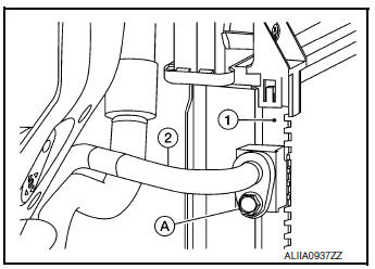
- Remove the bolt (A) that retains the high-pressure flexible hose (2) to the condenser (1).
CAUTION: Cap or wrap the joint of the pipe with suitable material such as vinyl tape to avoid the entry of air.
- Remove bolt (A) that retains high-pressure pipe (1) to condenser (2).
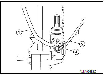
- Remove the condenser bracket bolts and condenser.
INSTALLATION
Installation is in the reverse order of removal.
CAUTION:
- Tighten bolts to specification. Refer to HA-32, "Exploded View".
- Do not reuse O-rings.
- Apply A/C oil to new O-rings for installation.
- After charging the refrigerant, check for leaks. Refer to HA-21, "Leak Test".
LIQUID TANK
LIQUID TANK : Removal and Installation
The liquid tank is serviced as an assembly with the condenser. Refer to HA-37, "CONDENSER : Removal and Installation".
REFRIGERANT PRESSURE SENSOR
REFRIGERANT PRESSURE SENSOR : Removal and Installation
REMOVAL
- Discharge the refrigerant. Refer to HA-23, "Recycle Refrigerant".
- Remove front air duct. Refer to EM-24, "Removal and Installation".
- Remove front bumper fascia. Refer to EXT-17, "Removal and Installation".
- Remove air guide (RH). Refer to HA-37, "Exploded View".
- Disconnect the harness connector from the refrigerant pressure sensor and remove.
CAUTION: Cap or wrap the opening of the refrigerant pressure sensor with suitable material such as vinyl tape to avoid the entry of air.
INSTALLATION
Installation is in the reverse order of removal.
CAUTION:
- Do not reuse O-ring.
- Apply A/C oil to new O-rings for installation.
- After charging the refrigerant, check for leaks. Refer to HA-21, "Leak Test".
 Cooler pipe and hose
Exploded View
Condenser
High-pressure flexible hose
Low-pressure flexible hose
Low-pressure pipe
Heating and cooling unit assembly
High-pressure pipe
Compressor
...
 Heating and cooling unit assembly
Exploded View
Steering Member
Heating and cooling unit assembly
Steering member
Bolt
Nut
Automatic Air Conditioning
Wiring harness
Air mix door duct (LH)
...
Other materials:
How to follow trouble diagnoses
Description
NOTICE:
Trouble diagnoses indicate work procedures required to diagnose problems
effectively. Observe the following
instructions before diagnosing.
Before performing trouble diagnoses, read the “Work Flow” in each
section.
After repairs, re-check that the pr ...
Hill start assist system
Hill start assist system
WARNING
Never rely solely on the hill start assist
system to prevent the vehicle from moving
backward on a hill. Always drive
carefully and attentively. Depress the
brake pedal when the vehicle is stopped
on a steep hill. Be especial ...
Monitor, climate, audio, phone and voice recognition systems
WARNING
Positioning of the heating or air conditioning
controls and display controls
should not be done while driving in order
that full attention may be given to
the driving operation.
Do not disassemble or modify this system.
If you do, it may result ...