Nissan Rogue Service Manual: Instrument lower panel LH
Removal and Installation
REMOVAL
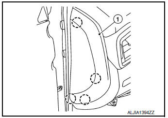
- Release instrument side finisher (LH) (1) pawls using a suitable
tool and remove.
 : Pawl
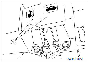
- Remove bolts (A) and fuel filler lid/hood lock release handle (1) from instrument lower panel LH.
- Remove data link cover from the instrument lower panel LH.
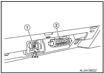
- Release the clip using a suitable tool and remove accessory
connector (1) from insturment lower panel LH.
 : Clip
 - Release the pawls using a suitable tool and remove data link
connector (2) from instrument lower panel LH.: Pawl
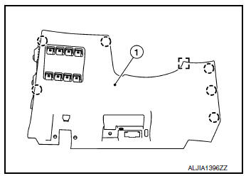
- Release the clips and pawls using a suitable tool, disconnect the harness connector and remove instrument lower panel LH (1).
: Pawl
 : Metal clip
INSTALLATION
Installation is in the reverse order of removal.
 Cluster lid C
Exploded View
Audio unit (AUDIO WITHOUT BOSE) /
AV control unit (AUDIO WITH BOSE)
(NAVIGATION WITH BOSE)
A/C switch assembly (AUTOMATIC
AIR CONDITIONING) / front air control
(M ...
 Glove box assembly and housing
Removal and Installation
REMOVAL
Release instrument side finisher (RH) (1) pawls using a suitable
tool and remove.
: Pawl
NOTE:
LH side shown; RH similar.
Release the glove box ...
Other materials:
Diagnosis and repair work flow
Work Flow
OVERALL SEQUENCE
DETAILED FLOW
1.INTERVIEW THE CUSTOMER FOR THE SYMPTOM
Interview the customer for the symptom (the condition and the environment
when the incident/malfunction
occurs).
>> GO TO 2.
2.CHECK SYMPTOM
Check the symptom from the customer information.
> ...
Basic inspection
DIAGNOSIS AND REPAIR WORK FLOW
Work flow
OVERALL SEQUENCE
DETAILED FLOW
1.OBTAIN INFORMATION ABOUT SYMPTOM
Interview the customer to obtain as much information as possible about the
conditions and environment under
which the malfunction occurred.
>> GO TO 2.
2.CHECK SYMPTOM
...
P014C, P014D, P015A, P015B, A/F sensor 1
DTC Description
DTC DETECTION LOGIC
To judge malfunctions, this diagnosis measures response time of the A/F
signal computed by ECM from the A/
F sensor 1 signal. The time is compensated by engine operating (speed and load),
fuel feedback control constant,
and the A/F sensor 1 temperature ind ...