Nissan Rogue Service Manual: Oil seal
VALVE OIL SEAL
VALVE OIL SEAL : Removal and Installation
REMOVAL
- Remove camshafts. Refer to EM-64, "Removal and Installation".
- Remove valve lifters. Refer to EM-56, "Disassembly and Assembly".
- Rotate crankshaft, and set piston whose valve oil seal is to be
removed to TDC. This will prevent valve
from dropping into cylinder.
CAUTION: When rotating crankshaft, be careful to avoid scarring front cover with timing chain.
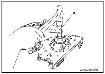
- Remove valve collet.
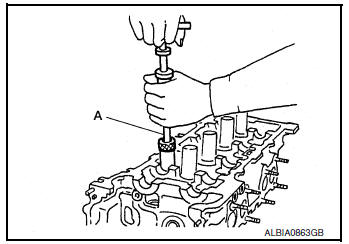
- Compress valve spring using suitable tool (A). Remove valve collet with a magnet.
CAUTION:
- Be careful not to damage valve lifter holes.
- Install suitable tool (A) in the center of valve spring retainer (1) to press it.
- Remove valve spring retainer and valve spring (with valve spring seat).
CAUTION: Do not remove valve spring seat from valve spring.
- Remove valve oil seal using suitable tool (A).
INSTALLATION
- Apply new engine oil to valve oil seal joint surface and seal lip.
- Press in valve oil seal to the height “H” as shown using suitable tool (A).
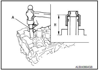
Height “H” : Refer to EM-118, "Cylinder Head"
- Installation of the remaining components is in the reverse order of removal
FRONT OIL SEAL
FRONT OIL SEAL : Removal and Installation
REMOVAL
- Remove engine undercover. Refer to EXT-37, "ENGINE UNDER COVER : Removal and Installation".
- Remove front fender protector. Refer to EXT-28, "FENDER PROTECTOR : Removal and Installation".
- Remove drive belt. Refer to EM-13, "Removal and Installation".
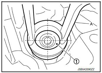
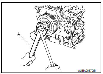
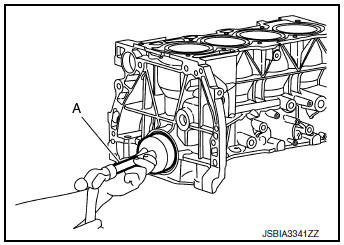
- Remove crankshaft pulley (1) using the following procedure:
- Hold the crankshaft pulley (1) using suitable tool (A), then loosen and remove the crankshaft pulley bolt.
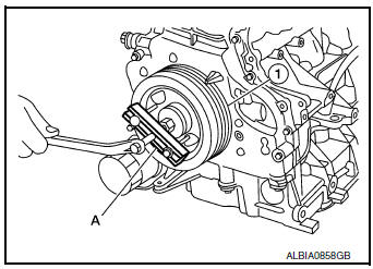
- Attach suitable tool (A) in the threaded hole on crankshaft pulley (1), and remove crankshaft pulley.
- Remove front oil seal with a suitable tool.
CAUTION: Do not damage front cover and crankshaft.
INSTALLATION
- Apply new engine oil to seal lip.
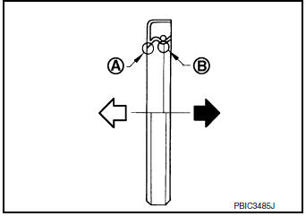
- Install front oil seal so that each seal lip is oriented as shown.
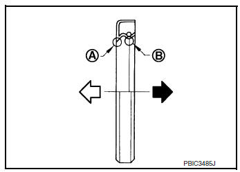
(A) : Dust seal lip
(B) : Oil seal lip
 : Engine outside
 : Engine inside
- Press-fit front oil seal until it is flush with front end surface of front cover using a suitable drift (A).
CAUTION:
- Do not damage front cover and crankshaft.
- Press-fit oil seal straight to avoid causing burrs or tilting.
- Do not touch the grease applied to the oil seal lip.
- Do not reuse oil seal.
- Insert crankshaft pulley by aligning with crankshaft key.
- Tap its center with a plastic hammer to insert.
- Do not tap the crankshaft pulley outer diameter.
- Tighten crankshaft pulley bolt.
- Secure crankshaft pulley with suitable tool to tighten the bolt.
- Perform angle tightening with the following procedure.
- Apply new engine oil to threads and seat surfaces of bolts.
- Apply a paint mark (A) on the front cover, mating with any one of six easy to recognize stamp marks on bolt flange (B).
- Tighten crankshaft bolt (1) to specification.
NOTE: Check that the assembled unit does not interfere with adjacent components by turning the crankshaft in the tightening direction.

Step 1 : 42.1 N·m (4.3 kg-m, 31 ft-lb)
Step 2 : Turn crankshaft bolt (1) an additional 60° +6°/
-0°.
- Installation of the remaining components is in the reverse order of removal.
REAR OIL SEAL
REAR OIL SEAL : Removal and Installation
REMOVAL
- Remove the engine and transaxle. Refer to EM-81, "Removal and Installation (FWD)" and EM-85, "Removal and Installation (AWD)".
- Separate engine from transaxle.
- Remove drive plate. Refer to EM-92, "Exploded View".
- Remove rear oil seal with a suitable tool.
CAUTION: Be careful not to damage crankshaft and cylinder block.
INSTALLATION
- Apply new engine oil to rear oil seal lip.
- Install rear oil seal so that each seal lip is oriented as shown.
(A) : Dust seal lip
(B) : Oil seal lip
 : Engine outside
 : Engine inside
- Press-fit rear oil seal with a suitable drift.
CAUTION:
- Do not damage crankshaft and cylinder block.
- Press-fit oil seal straight to avoid causing burrs or tilting.
- Do not touch grease applied onto oil seal lip.
- Apply neutral detergent (if needed) to outer circumference of oil seal to aid installation. Do not allow detergent to contact inner circumference of oil seal.
- Press in the new rear oil seal (1) to the position as shown.
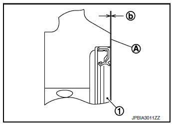
(A) : Rear end surface of cylinder block
(b) : 0.0 mm - 0.5 mm (0.000 in - 0.020 in)
- Installation of the remaining components is in the reverse order of removal.
 Valve timing control
Exploded View
Valve timing cover
2. O-rings
Intake valve timing intermediate
lock control solenoid valve
Intake valve timing control solenoid
valve
Exhaust valve timi ...
 Unit removal and installation
ENGINE ASSEMBLY
Exploded view
Engine mounting insulator (RH)
Upper torque rod (RH)
Engine mounting bracket (RH)
Lower torque rod
Torque rod bracket
Engi ...
Other materials:
Periodic maintenance
TRANSFER OIL
Inspection
TRANSFER OIL LEAKS
Check that transfer oil is not leaking from transfer assembly or around it.
TRANSFER OIL LEVEL
CAUTION:
Do not start engine while checking transfer oil level.
Remove filler plug (1) and gasket.
: Front
Transfer oil level (A) should be l ...
P0713 transmission fluid temperature sensor A
DTC Description
DTC DETECTION LOGIC
DTC
CONSULT screen terms
(Trouble diagnosis content)
DTC detection condition
P0713
FLUID TEMP SENSOR A
(Transmission Fluid Temperature Sensor A Circuit
High)
When all of the following conditions are satisfied and this state i ...
Unit disassembly and assembly
STEERING GEAR AND LINKAGE
Exploded View
DISASSEMBLY AND ASSEMBLY
Steering gear
Inner boot clamp
Boot
Outer boot clamp
Outer socket
Disassembly and Assembly
DISASSEMBLY
Remove outer socket lock nut and remove outer socket.
Remove inne ...