Nissan Rogue Service Manual: P0182, P0183 FTT sensor
DTC Description
DTC DETECTION LOGIC
| DTC No. | CONSULT screen terms (Trouble diagnosis content) | DTC detecting condition |
| P0182 | FTT SEN/CIRCUIT (Fuel temperature sensor ″A″ circuit low) | An excessively low voltage from the sensor is sent to ECM. |
| P0183 | FTT SEN/CIRCUIT (Fuel temperature sensor ″A″ circuit high) | An excessively high voltage from the sensor is sent to ECM. |
POSSIBLE CAUSE
- Harness or connectors (The FTT sensor circuit is open or shorted.)
- Fuel tank temperature sensor
- Combination meter
FAIL-SAFE
Not applicable
DTC CONFIRMATION PROCEDURE
1.PRECONDITIONING
If DTC Confirmation Procedure has been previously conducted, always perform the following procedure before conducting the next test.
- Turn ignition switch OFF and wait at least 10 seconds.
- Turn ignition switch ON.
- Turn ignition switch OFF and wait at least 10 seconds.
>> GO TO 2.
2.PERFORM DTC CONFIRMATION PROCEDURE
- Turn ignition switch ON and wait at least 5 seconds.
- Check 1st trip DTC.
Is 1st trip DTC detected? YES >> Proceed to EC-274, "Diagnosis Procedure".
NO >> INSPECTION END
Diagnosis Procedure
1.CHECK DTC WITH COMBINATION METER
Refer to MWI-21, "CONSULT Function (METER/M&A)".
Is the inspection result normal? YES >> GO TO 2.
NO >> Proceed to MWI-62, "Component Function Check".
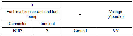
2.CHECK FUEL TANK TEMPERATURE (FTT) SENSOR POWER SUPPLY
- Turn ignition switch OFF.
- Disconnect fuel level sensor unit and fuel pump harness connector.
- Turn ignition switch ON.
- Check the voltage between fuel level sensor unit and fuel pump harness connector and ground.
Is the inspection result normal? YES >> GO TO 4.
NO >> GO TO 3.
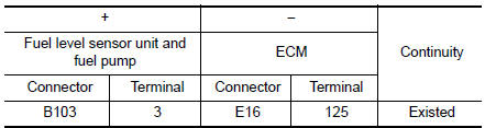
3.CHECK FUEL TANK TEMPERATURE (FTT) SENSOR POWER SUPPLY CIRCUIT
- Turn ignition switch OFF.
- Disconnect ECM harness connector.
- Check the continuity between fuel level sensor unit and fuel pump harness connector and ECM harness connector.
- Also check harness for short to ground and to power.
Is the inspection result normal? YES >> Perform the trouble diagnosis for power supply circuit.
NO >> Repair or replace error-detected parts.
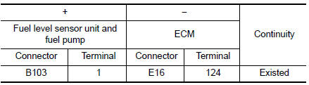
4.CHECK FUEL TANK TEMPERATURE (FTT) SENSOR GROUND CIRCUIT
- Turn ignition switch OFF.
- Disconnect ECM connector.
- Check the continuity between fuel level sensor unit and fuel pump harness connector and ECM harness connector.
- Also check harness for short to power.
Is the inspection result normal? YES >> GO TO 5.
NO >> Repair or replace error-detected parts.
5.CHECK FUEL TANK TEMPERATURE (FTT) SENSOR
Check the FTT sensor. Refer to EC-276, "Component Inspection".
Is the inspection result normal? YES >> GO TO 6.
NO >> Replace “fuel level sensor unit and fuel pump”. Refer to FL-6, "Removal and Installation".
6.CHECK INTERMITTENT INCIDENT
Refer to GI-41, "Intermittent Incident".
>> INSPECTION END
Component Inspection
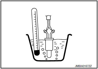
1.CHECK FUEL TANK TEMPERATURE (FTT) SENSOR
- Turn ignition switch OFF.
- Disconnect fuel level sensor unit and fuel pump harness connector.
- Remove fuel level sensor unit. Refer to FL-6, "Removal and Installation".
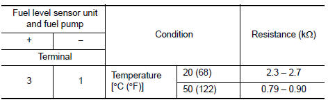
- Check resistance between fuel level sensor unit and fuel pump terminals by heating with hot water as shown in the figure.
Is the inspection result normal? YES >> INSPECTION END
NO >> Replace fuel level sensor unit and fuel pump. Refer to FL-6, "Removal and Installation".
 P0181 FTT sensor
DTC Description
DTC DETECTION LOGIC
DTC No.
CONSULT screen terms
(Trouble diagnosis content)
DTC detecting condition
P0181
FTT SENSOR
(Fuel temperature sensor ″A ...
 P0196 EOT sensor
DTC Description
DTC DETECTION LOGIC
DTC No.
CONSULT screen terms
(Trouble diagnosis content)
DTC detecting condition
P0196
EOT SENSOR
(Engine oil temperature sensor ra ...
Other materials:
C1730, C1731, C1732, C1733 flat tire
DTC Logic
NOTE:
The Signal Tech II Tool [- (J-50190)] can be used to perform the following
functions. Refer to the Signal Tech II
User Guide for additional information.
Activate and display TPMS sensor IDs
Display tire pressure reported by the TPMS sensor
Read TPMS DTC ...
U0101 CAN comm circuit
Description
CAN (Controller Area Network) is a serial communication line for real time
application. It is an on-vehicle multiplex
communication line with high data communication speed and excellent error
detection ability. Many electronic
control units are equipped onto a vehicle, and each co ...
Back door finisher
Exploded View
Back door
Access cover
Back door finisher
Clip
Pawl
Metal clip
Removal and Installation
REMOVAL
Using a suitable tool (A) release upper LH most clip, then
release remaining clips by gently pulling down on back door finisher
(1).
: Clip
INSTA ...