Nissan Rogue Service Manual: P0448 EVAP canister vent control valve
DTC Description
DTC DETECTION LOGIC
| DTC No. | CONSULT screen terms (Trouble diagnosis content) | DTC detecting condition |
| P0448 | VENT CONTROL VALVE (Evaporative emission system vent control circuit shorted) | EVAP canister vent control valve remains closed under specified driving conditions. |
POSSIBLE CAUSE
- EVAP canister vent control valve
- EVAP control system pressure sensor and the circuit
- Blocked rubber tube to EVAP canister vent control valve
- EVAP canister is saturated with water
FAIL-SAFE
Not applicable
DTC CONFIRMATION PROCEDURE
1.PRECONDITIONING
If DTC Confirmation Procedure has been previously conducted, always perform the following procedure before conducting the next test.
- Turn ignition switch OFF and wait at least 10 seconds.
- Turn ignition switch ON.
- Turn ignition switch OFF and wait at least 10 seconds.
>> GO TO 2.
2.PERFORM DTC CONFIRMATION PROCEDURE
 With CONSULT
- Turn ignition switch ON and wait at least 5 seconds.
- Turn ignition switch OFF and wait at least 10 seconds.
- Turn ignition switch ON and select ŌĆ£DATA MONITORŌĆØ mode of ŌĆ£ENGINEŌĆØ using CONSULT.
- Start engine and let it idle for at least 1 minute.
- Repeat next procedures three times.
- Increase the engine speed up to 3,000 to 3,500 rpm and keep it for
2 minutes and 50 seconds to 3 minutes.
Never exceed 3 minutes.
- Fully released accelerator pedal and keep engine idle for about 5 seconds.
- Repeat next procedure 20 times.
- Quickly increase the engine speed up to 4,000 to 4,500 rpm or more and keep it for 25 to 30 seconds.
- Fully released accelerator pedal and keep engine idle for at least 35 seconds.
- Check 1st trip DTC.
 With GST
Follow the procedure ŌĆ£With CONSULTŌĆØ above.
Is 1st trip DTC detected?
YES >> Proceed to EC-324, "Diagnosis Procedure".
NO >> INSPECTION END
Diagnosis Procedure
1.CHECK RUBBER TUBE
- Turn ignition switch OFF.
- Disconnect rubber tube connected to EVAP canister vent control valve.
- Check the rubber tube for clogging.
Is the inspection result normal? YES >> GO TO 2.
NO >> Clean rubber tube using an air blower.
2.CHECK EVAP CANISTER VENT CONTROL VALVE
Check the EVAP canister vent control valve. Refer to EC-325, "Component Inspection".
Is the inspection result normal? YES >> GO TO 3.
NO >> Replace EVAP canister vent control valve. Refer to FL-21, "Removal and Installation".
3.CHECK IF EVAP CANISTER IS SATURATED WITH WATER
- Remove EVAP canister with EVAP canister vent control valve and EVAP control system pressure sensor attached.
- Check if water will drain from the EVAP canister.
Does water drain from EVAP canister? YES >> GO TO 4.
NO >> GO TO 6.
4.CHECK EVAP CANISTER
Weigh the EVAP canister with the EVAP canister vent control valve and EVAP control system pressure sensor attached.
The weight should be less than 2.1 kg (4.6 lb).
Is the inspection result normal? YES >> GO TO 6.
NO >> GO TO 5.
5.DETECT MALFUNCTIONING PART
Check the following.
- EVAP canister for damage
- EVAP hose between EVAP canister and vehicle frame for clogging or poor connection
>> Repair hose or replace EVAP canister. Refer to FL-19, "Removal and Installation".
6.CHECK EVAP CONTROL SYSTEM PRESSURE SENSOR CONNECTOR
- Disconnect EVAP control system pressure sensor harness connector.
- Check connectors for water.
Water should not exist.
Is the inspection result normal? YES >> GO TO 7.
NO >> Replace EVAP control system pressure sensor. Refer to FL-22, "Removal and Installation".
7.CHECK EVAP CONTROL SYSTEM PRESSURE SENSOR
Check the EVAP control system pressure sensor. Refer to EC-330, "Component Inspection".
Is the inspection result normal? YES >> GO TO 8.
NO >> Replace EVAP control system pressure sensor. Refer to FL-22, "Removal and Installation".
8.CHECK INTERMITTENT INCIDENT
Refer to GI-41, "Intermittent Incident".
>> INSPECTION END
Component Inspection
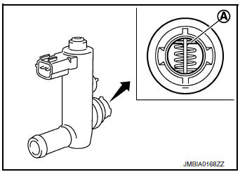
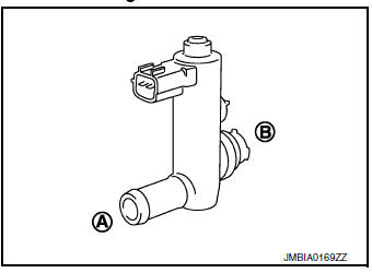
1.CHECK EVAP CANISTER VENT CONTROL VALVE-1
- Turn ignition switch OFF.
- Remove EVAP canister vent control valve from EVAP canister.
- Check portion A of EVAP canister vent control valve for being rusted.
Is it rusted? YES >> Replace EVAP canister vent control valve. Refer to FL- 21, "Removal and Installation".
NO >> GO TO 2.
2.CHECK EVAP CANISTER VENT CONTROL VALVE-2
 With CONSULT
- Reconnect harness connectors disconnected.
- Turn ignition switch ON.
- Perform ŌĆ£VENT CONTROL/VŌĆØ in ŌĆ£ACTIVE TESTŌĆØ mode of ŌĆ£ENGINEŌĆØ using CONSULT.
- Check air passage continuity and operation delay time.
Make sure new O-ring is installed properly.
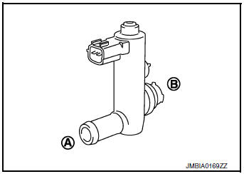
| Condition (VENT CONT/V) | Air passage continuity between A and B |
| ON | Not existed |
| OFF | Existed |
Operation takes less than 1 second.
 Without CONSULT
Check air passage continuity and operation delay time under the following conditions.
Make sure new O-ring is installed properly.
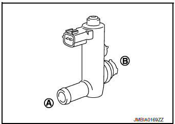
| Condition | Air passage continuity between A and B |
| 12 V direct current supply between terminals 1 and 2 | Not existed |
| OFF | Existed |
Operation takes less than 1 second.
Is the inspection result normal? YES >> GO TO 3.
NO >> Replace EVAP canister vent control valve. Refer to FL-21, "Removal and Installation".
3.CHECK EVAP CANISTER VENT CONTROL VALVE-3
 With CONSULT
- Clean the air passage [portion A to B] of EVAP canister vent control valve using an air blower.
- Perform ŌĆ£VENT CONTROL/VŌĆØ in ŌĆ£ACTIVE TESTŌĆØ mode of ŌĆ£ENGINEŌĆØ using CONSULT.
- Check air passage continuity and operation delay time.
Make sure new O-ring is installed properly.

| Condition (VENT CONT/V) | Air passage continuity between A and B |
| ON | Not existed |
| OFF | Existe |
Operation takes less than 1 second.
Without CONSULT
- Clean the air passage [portion A to B] of EVAP canister vent control valve using an air blower.
- Check air passage continuity and operation delay time under the
following conditions.
Make sure new O-ring is installed properly.
| Condition | Air passage continuity between A and B |
| 12 V direct current supply between terminals 1 and 2 | Not existed |
| OFF | Existed |
Operation takes less than 1 second.
Is the inspection result normal? YES >> INSPECTION END
NO >> Replace EVAP canister vent control valve. Refer to FL-21, "Removal and Installation".
 P0447 EVAP canister vent control valve
DTC Description
DTC DETECTION LOGIC
DTC No.
CONSULT screen terms
(Trouble diagnosis content)
DTC detecting condition
P0447
VENT CONTROL VALVE
(Evaporative emission sys ...
 P0451 EVAP control system pressure sensor
DTC Description
DTC DETECTION LOGIC
DTC No.
CONSULT screen terms
(Trouble diagnosis content)
DTC detecting condition
P0451
EVAP SYS PRES SEN
(Evaporative emission syst ...
Other materials:
Thermostat and water control
valve
Exploded View
Water inlet
Thermostat
Rubber ring
To radiator hose (lower)
NOTE:
When removing components such as hoses, tubes/lines, etc., cap or plug openings
to prevent fluid from spilling.
Removal and Installation
WARNING:
Do not remove the radiator ...
Basic inspection
DIAGNOSIS AND REPAIR WORKFLOW
Work Flow
OVERALL SEQUENCE
DETAILED FLOW
1.GET INFORMATION FOR SYMPTOM
Get detailed information from the customer about the symptom (the condition
and the environment when the
incident/malfunction occurred).
>> GO TO 2.
2.CONFIRM THE SYMPTOM
Try t ...
P0172 fuel injection system function
DTC Description
DTC DETECTION LOGIC
With the Air/Fuel Mixture Ratio Self-Learning Control, the actual mixture
ratio can be brought closely to the
theoretical mixture ratio based on the mixture ratio feedback signal from the
A/F sensors 1. The ECM calculates
the necessary compensation to corr ...