Nissan Rogue Service Manual: Power supply and ground circuit
BCM (BODY CONTROL SYSTEM) (WITH INTELLIGENT KEY SYSTEM)
BCM (BODY CONTROL SYSTEM) (WITH INTELLIGENT KEY SYSTEM) : Diagnosis Procedure
Regarding Wiring Diagram information, refer to BCS-50, "Wiring Diagram".
1. CHECK FUSE
Check that the following fuse is not blown.

Is the fuse blown? YES >> Replace the blown fuse after repairing the affected circuit.
NO >> GO TO 2.
2. CHECK POWER SUPPLY CIRCUIT
- Disconnect BCM connector M20.
- Check voltage between BCM connector M20 and ground.
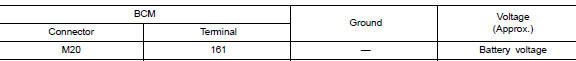
Is the inspection result normal? YES >> GO TO 3.
NO >> Repair or replace harness or connectors.
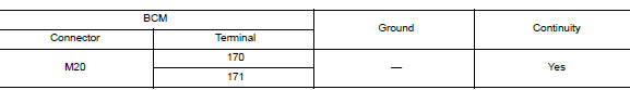
3. CHECK GROUND CIRCUIT
Check continuity between BCM connector M20 and ground.

Is the inspection result normal? YES >> Inspection End.
NO >> Repair or replace harness or connectors.
BCM (BODY CONTROL SYSTEM) (WITHOUT INTELLIGENT KEY SYSTEM)
BCM (BODY CONTROL SYSTEM) (WITHOUT INTELLIGENT KEY SYSTEM) : Diagnosis Procedure
Regarding Wiring Diagram information, refer to BCS-110, "Wiring Diagram".
1. CHECK FUSE
Check that the following fuse is not blown.

Is the fuse blown? YES >> Replace the blown fuse after repairing the affected circuit.
NO >> GO TO 2.
2. CHECK POWER SUPPLY CIRCUIT
- Disconnect BCM connector M20.
- Check voltage between BCM connector M20 and ground.
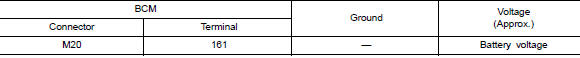
Is the inspection result normal? YES >> GO TO 3.
NO >> Repair or replace harness or connectors.
3. CHECK GROUND CIRCUIT
Check continuity between BCM connector M20 and ground.
Is the inspection result normal? YES >> Inspection End.
NO >> Repair or replace harness or connectors.
MOONROOF MOTOR ASSEMBLY
MOONROOF MOTOR ASSEMBLY : Description
- BCM supplies the moonroof motor assembly with power.
- CPU is integrated in moonroof motor assembly.
- Tilts up/down & slides open/close by moonroof switch operation.
- In order to close the moonroof during high speed driving, the Combination meter will send a speed signal to the moonroof CPU to adjust the torque of the motor during the tilt-down operation.
MOONROOF MOTOR ASSEMBLY : Component Function Check
1. CHECK MOONROOF MOTOR FUNCTION
Does the tilt up/down & slide open/close functions operate normally with moonroof switch? Is the inspection result normal? YES >> Moonroof motor assembly is OK.
NO >> Refer to RF-26, "MOONROOF MOTOR ASSEMBLY : Diagnosis Procedure".
MOONROOF MOTOR ASSEMBLY : Diagnosis Procedure
Regarding Wiring Diagram information, refer to RF-17, "Wiring Diagram".
MOONROOF MOTOR ASSEMBLY
1. CHECK POWER SUPPLY CIRCUIT
- Turn ignition switch OFF.
- Disconnect the moonroof motor assembly connector.
- Turn ignition switch ON.
- Check voltage between moonroof motor assembly connector and ground.
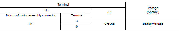
Is the inspection result normal? YES >> GO TO 2.
NO >> GO TO 3.
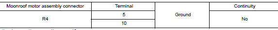
2. CHECK GROUND CIRCUIT
- Turn ignition switch OFF.
- Check continuity between moonroof motor assembly connector and ground.

Is the inspection result normal? YES >> GO TO 5.
NO >> Repair or replace harness.
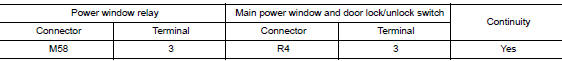
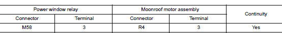
3.CHECK HARNESS CONTINUITY
- Turn ignition switch OFF.
- Disconnect power window relay connector.
- Check continuity between power window relay harness connector and moonroof motor assembly harness connector.
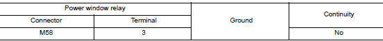
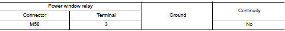
- Check continuity between power window relay harness connector and ground.
Is the inspection result normal? YES >> Refer to PWC-48, "Diagnosis Procedure".
NO >> Repair or replace harness.
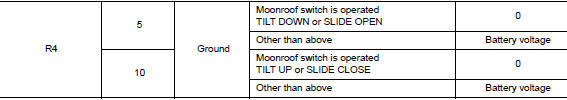
4. CHECK MOONROOF SWITCH INPUT SIGNAL
- Connect moonroof motor assembly.
- Turn ignition switch ON.
- Check voltage between the moonroof motor assembly connector and ground.

Is the inspection result normal? YES >> GO TO 8.
NO >> GO TO 6.
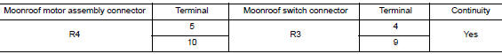
5. CHECK MOONROOF SWITCH CIRCUIT
- Turn ignition switch OFF.
- Disconnect the moonroof motor assembly and moonroof switch.
- Check continuity between the moonroof motor assembly connector and moonroof switch connector.
- Check continuity between the moonroof motor assembly connector and ground.
Is the inspection result normal? YES >> GO TO 7.
NO >> Repair or replace harness.
6. CHECK MOONROOF SWITCH GROUND CIRCUIT
- Connect moonroof motor assembly.
- Check continuity between the moonroof switch connector and ground.

Is the inspection result normal? YES >> Refer to RF-32, "Component Inspection".
NO >> Repair or replace harness.
7. CHECK COMBINATION METER SIGNAL
- Connect the moonroof motor assembly connector.
- Turn ignition switch ON.
- Check the signal between the moonroof motor assembly connector and ground with oscilloscope.
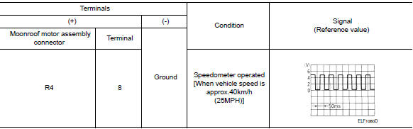
Is the inspection result normal? YES >> Replace moonroof motor assembly. Refer to RF-53, "Removal and Installation". After that, refer to RF-24, "ADDITIONAL SERVICE WHEN REPLACING CONTROL UNIT : Special Repair Requirement".
NO >> GO TO 9.
8.CHECK COMBINATION METER CIRCUIT
- Turn ignition switch OFF.
- Disconnect combination meter.
- Check continuity between the combination meter connector and the moonroof motor assembly connector.

- Check continuity between the combination meter connector and ground.

Is the inspection result normal? YES >> Replace combination meter. Refer to BCS-76, "Removal and Installation".
NO >> Repair or replace harness.
MOONROOF MOTOR ASSEMBLY : Special Repair Requirement
1. PERFORM INITIALIZATION PROCEDURE
Perform the initialization procedure.
Refer to RF-29, "MOONROOF MOTOR ASSEMBLY : Special Repair Requirement".
>> GO TO 2.
2. CHECK ANTI-PINCH OPERATION
Check the anti-pinch operation.
Refer to RF-29, "MOONROOF MOTOR ASSEMBLY : Special Repair Requirement".
Is the inspection result normal? YES >> Inspection End.
NO >> Check fitting adjustment.
SUNSHADE MOTOR ASSEMBLY
SUNSHADE MOTOR ASSEMBLY : Description
- BCM supplies the sunshade motor assembly with power.
- CPU is integrated in sunshade motor assembly.
- Slide open/close controlled by the moonroof switch operation.
SUNSHADE MOTOR ASSEMBLY : Component Function Check
1. CHECK SUNSHADE MOTOR FUNCTION
Does the slide open and close functions operate normally with the moonroof switch? Is the inspection result normal? YES >> Sunshade motor assembly is OK.
NO >> Refer to RF-29, "SUNSHADE MOTOR ASSEMBLY : Diagnosis Procedure".
SUNSHADE MOTOR ASSEMBLY : Diagnosis Procedure
1.CHECK POWER SUPPLY
- Turn ignition switch OFF.
- Disconnect sunshade motor assembly connector.
- Turn ignition switch ON.
- Check voltage between sunshade motor assembly harness connector and ground.
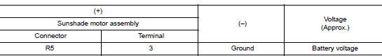
Is the inspection result normal? YES >> GO TO 2.
NO >> GO TO 3.
2.CHECK GROUND CIRCUIT
- Turn ignition switch OFF.
- Check continuity between sunshade motor assembly harness connector and ground.
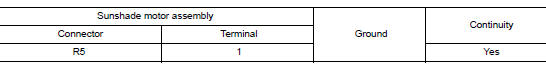
Is the inspection result normal? YES >> GO TO 4.
NO >> Repair or replace the harness.
3.CHECK HARNESS CONTINUITY
- Turn ignition switch OFF.
- Disconnect power window relay connector.
- Check continuity between power window relay harness connector and moonroof motor assembly harness connector.
- Check continuity between power window relay harness connector and ground.
Is the inspection result normal? YES >> Refer to PWC-48, "Diagnosis Procedure".
NO >> Repair or replace harness.

 Moonroof switch
Description
Transmits switch operation signal to moonroof motor and sunshade motor
assembly.
Diagnosis Procedure
Regarding Wiring Diagram information, refer to RF-17, "Wiring Diagram".
...
Other materials:
P1078 EVT control position sensor
DTC Description
DTC DETECTION LOGIC
DTC No.
CONSULT screen terms
(Trouble diagnosis content)
DTC detecting condition
P1078
EXH TIM SEN/CIRC-B1
(EXH TIM SEN/CIRC-B1)
An excessively high or low voltage from the sensor is sent to ECM.
POSSIBLE CAUSE
H ...
Preparation
PREPARATION
Special Service Tool
The actual shape of the tools may differ from those illustrated here.
Tool number
(TechMate No.)
Tool name
Description
KV40107300
( — )
Boot band crimping tool
Installing boot band
KV40107500
( — )
...
P050A, P050B, P050E cold start control
Description
ECM controls ignition timing and engine idle speed when engine is started
with pre-warming up condition.
This control promotes the activation of three way catalyst by heating the
catalyst and reduces emissions.
DTC Description
DTC DETECTION LOGIC
DTC No.
CONSULT scre ...