Nissan Rogue Service Manual: Moonroof switch
Description
Transmits switch operation signal to moonroof motor and sunshade motor assembly.
Diagnosis Procedure
Regarding Wiring Diagram information, refer to RF-17, "Wiring Diagram".
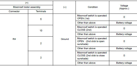
1.CHECK MOONROOF SWITCH INPUT SIGNAL
- Turn ignition switch ON.
- Check voltage between moonroof motor assembly harness connector and ground.
Is the inspection result normal? YES >> Inspection End.
NO >> GO TO 2.
2.CHECK MOONROOF SWITCH CIRCUIT
- Turn ignition switch OFF.
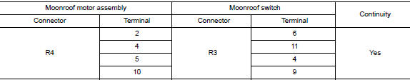
- Disconnect moonroof motor assembly connector and moonroof switch connector.
- Check continuity between moonroof motor assembly harness connector and moonroof switch harness connector.
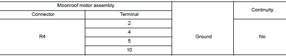
- Check continuity between moonroof motor assembly harness connector and ground.
Is the inspection result normal? YES >> GO TO 3.
NO >> Repair or replace the harness.
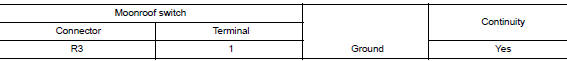
3.CHECK MOONROOF SWITCH GROUND CIRCUIT
Check continuity between moonroof switch harness connector and ground.
Is the inspection result normal? YES >> GO TO 4.
NO >> Repair or replace the harness.
4.CHECK MOONROOF SWITCH
Check moonroof switch.
Refer to RF-32, "Component Inspection".
Is the inspection result normal? YES >> GO TO 5.
NO >> Replace moonroof switch. Refer to RF-64, "Removal and Installation".
5.CHECK INTERMITTENT INCIDENT
Refer to GI-41, "Intermittent Incident".
>> Inspection End.
Component Inspection
MOONROOF SWITCH
1. CHECK MOONROOF SWITCH
- Turn ignition switch OFF.
- Disconnect moonroof switch.
- Check continuity between moonroof switch terminals.
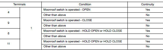
Is the inspection result normal? YES >> Moonroof switch is OK.
NO >> Replace moonroof switch. Refer to RF-64, "Removal and Installation".
 Power supply and ground circuit
BCM (BODY CONTROL SYSTEM) (WITH INTELLIGENT KEY SYSTEM)
BCM (BODY CONTROL SYSTEM) (WITH INTELLIGENT KEY SYSTEM) : Diagnosis
Procedure
Regarding Wiring Diagram information, refer to BCS-50, "Wi ...
 Door switch
WITH INTELLIGENT KEY
WITH INTELLIGENT KEY : Component Function Check
1.CHECK FUNCTION
Select "DOOR LOCK" of "BCM" using CONSULT.
Select "DOOR SW-DR", ...
Other materials:
U1000 CAN COMM CIRCUIT
Description
CAN (Controller Area Network) is a serial communication line for real time
application. It is an on-vehicle multiplex
communication line with high data communication speed and excellent error
detection ability. Many electronic
control units are equipped onto a vehicle, and each co ...
Rear window defogger and door mirror defogger do not operate
Diagnosis Procedure
Regarding Wiring Diagram information, refer to DEF-12, "Wiring Diagram".
1. CHECK REAR WINDOW DEFOGGER SWITCH
Check rear window defogger switch.
Refer to DEF-22, "WITH MANUAL A/C : Component Function Check".
Is the inspection result normal?
YES >& ...
Service data and specifications (SDS)
Oil Pressure
*: Engine oil temperature at 80°C (176°F)
Oil Pump
Relief Valve
Oil Capacity
...