Nissan Rogue Service Manual: Power supply and ground circuit
Diagnosis Procedure
1.CHECK FUSE
Check that the following fuse is not fusing.
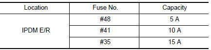
Is the fuse fusing? YES >> Replace the fuse after repairing the applicable circuit.
NO >> GO TO 2.
2.CHECK GROUND CONNECTION
- Turn ignition switch OFF.
- Check ground connection E9 or E15. Refer to GI-44, "Circuit Inspection".
Is the inspection result normal? YES >> GO TO 3.
NO >> Repair or replace ground connection.
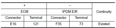
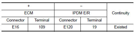
3.CHECK ECM GROUND CIRCUIT
- Disconnect ECM harness connectors.
- Check the continuity between ECM harness connector and ground.
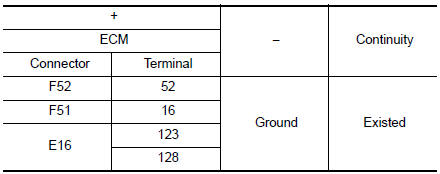
Is the inspection result normal? YES >> GO TO 4.
NO >> Repair or replace error-detected parts.
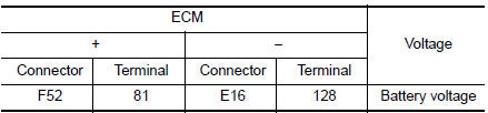
4.CHECK ECM POWER SUPPLY (MAIN)-1
- Reconnect ECM harness connector.
- Turn ignition switch ON.
- Check the voltage between ECM harness connector terminals.
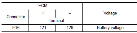
Is the inspection result normal? YES >> GO TO 5.
NO >> GO TO 6.
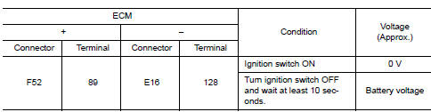
5.CHECK ECM POWER SUPPLY (MAIN)--2
- Turn ignition switch OFF and wait at least 10 seconds.
- Check the voltage between ECM harness connector terminals as per the following.
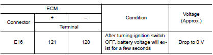
Is the inspection result normal? YES >> GO TO 9.
NO >> GO TO 7.
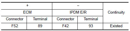
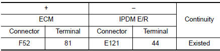
6.CHECK ECM POWER SUPPLY (MAIN) CIRCUIT
- Turn ignition switch OFF.
- Disconnect ECM harness connectors.
- Disconnect IPDM E/R harness connector.
- Check the continuity between ECM harness connector and IPDM E/R harness connector.
- Also check harness for short to ground.
Is the inspection result normal? YES >> Perform the trouble diagnosis for power supply circuit.
NO >> Repair or replace error-detected parts.
7.CHECK ECM RELAY CONTROL SIGNAL
Check the voltage between ECM harness connector terminals as per the following.
Is the inspection result normal? YES >> Check Intermittent Incident. Refer to GI-41, "Intermittent Incident".
NO >> GO TO 8.
8.CHECK ECM RELAY CONTROL SIGNAL CIRCUIT
- Turn ignition switch OFF.
- Disconnect ECM harness connector.
- Disconnect IPDM E/R harness connector
- Check the continuity between ECM harness connector and IPDM E/R harness connector.
- Also check harness for short to ground and to power.
Is the inspection result normal? YES >> Replace IPDM E/R. Refer to PCS-35, "Removal and Installation".
NO >> Repair or replace error-detected parts.
9.CHECK IGNITION SWITCH SIGNAL
- Turn ignition switch ON.
- Check the voltage between ECM harness connector terminals.
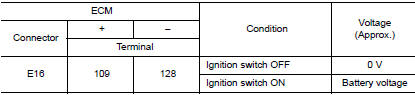
Is the inspection result normal? YES >> GO TO 11.
NO >> GO TO 10.
10.CHECK IGNITION SWITCH SIGNAL CIRCUIT
- Turn ignition switch OFF.
- Disconnect ECM harness connector.
- Disconnect IPDM E/R harness connector.
- Check the continuity between ECM harness connector and IPDM E/R harness connector.
- Also check harness for short to ground and to power.
Is the inspection result normal? YES >> Perform the trouble diagnosis for power supply circuit.
NO >> Repair or replace error-detected parts.
11.CHECK ECM POWER SUPPLY (BACK-UP)
Check the voltage between ECM harness connector terminals.
Is the inspection result normal? YES >> Check Intermittent Incident. Refer to GI-41, "Intermittent Incident".
NO >> GO TO 12.
12.CHECK ECM POWER SUPPLY (BACK-UP) CIRCUIT
- Turn ignition switch OFF.
- Disconnect ECM harness connector.
- Disconnect IPDM E/R harness connector.
- Check the continuity between ECM harness connector and IPDM E/R harness connector.
- Also check harness for short to ground and to power.
Is the inspection result normal? YES >> Perform the trouble diagnosis for power supply circuit.
NO >> Repair or replace error-detected parts.
 Trouble diagnosis - specification value
Description
The specification (SP) value indicates the tolerance of the value that is
displayed in ŌĆ£SPECŌĆØ of ŌĆ£DATA MONITORŌĆØ
mode of CONSULT during normal operation of the Engine Control Sy ...
 U0101 CAN comm circuit
Description
CAN (Controller Area Network) is a serial communication line for real time
application. It is an on-vehicle multiplex
communication line with high data communication speed and excellen ...
Other materials:
Component parts
Component Parts Location
Steering column assembly
No.
Component
Function
1
ABS actuator and electric unit (control unit)
Transmits the following signal to EPS control unit via CAN
communication.
Vehicle speed signal (ABS)
...
Anti-lock Braking System (ABS)
WARNING
The Anti-lock Braking System (ABS) is a
sophisticated device, but it cannot prevent
accidents resulting from careless
or dangerous driving techniques. It can
help maintain vehicle control during
braking on slippery surfaces. Remember
that stopping dis ...
ECU diagnosis information
DIAGNOSIS SENSOR UNIT
DTC Index
DIAGNOSTIC CODE CHART
NOTE:
Follow the procedures in numerical order when repairing malfunctioning parts.
Confirm whether malfunction is
eliminated using air bag warning lamp or CONSULT each time repair is finished.
If malfunction is still
observed, proceed ...