Nissan Rogue Service Manual: Power supply and ground circuit
Diagnosis Procedure
Regarding Wiring Diagram information, refer to PCS-24, "Wiring Diagram".
1. CHECK FUSE AND FUSIBLE LINKS
Check that the following IPDM E/R fuse or fusible links are not blown.
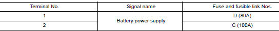
Is the fuse blown? YES >> Replace the blown fuse or fusible link after repairing the affected circuit.
NO >> GO TO 2.
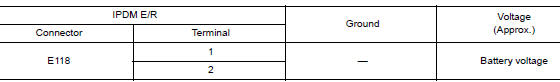
2. CHECK BATTERY POWER SUPPLY CIRCUIT
- Disconnect IPDM E/R connector E118.
- Check voltage between IPDM E/R connector E118 and ground.
Is the inspection result normal? YES >> GO TO 3.
NO >> Repair or replace harness or connectors.
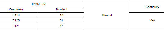
3. CHECK GROUND CIRCUIT
- Disconnect IPDM E/R connectors E119, E120 and E121.
- Check continuity between IPDM E/R connectors and ground.
Is the inspection result normal? YES >> Inspection End.
NO >> Repair or replace harness or connectors.
 U1000 CAN COMM CIRCUIT
Description
CAN communication allows a high rate of information transmission through the
two communication lines
(CAN-H line and CAN-L line) connecting various control units in the system. Each
...
 Parking brake switch
Component Function Check
1.CHECK PARKING BRAKE SWITCH OPERATION
Check that brake warning lamp in combination meter turns ON/OFF when parking
brake is operated.
Is the inspection result normal?
...
Other materials:
Unit disassembly and assembly
FRONT COMBINATION LAMP
Exploded View
Front combination lamp
Parking (side marker) lamp bulb socket
Headlamp (low beam) bulb
Plastic cover
Headlamp (high beam) bulb
Turn signal lamp bulb socket
Disassembly and Assembly
DISASSEMBLY
Remove front combinat ...
Charging system preliminary inspection
Diagnosis Procedure
1.CHECK BATTERY TERMINALS CONNECTION
Check if battery terminals are clean and tight.
Is the inspection result normal?
YES >> GO TO 2.
NO >> Repair battery terminal connection. Confirm repair by performing complete
Charging system test
using EXP-800 NI or G ...
U0155 lost communication (IPC)
DTC Description
DTC DETECTION LOGIC
DTC
CONSULT screen terms
(Trouble diagnosis content)
DTC detection condition
U0155
LOST COMM (IPC)
[Lost Communication With Instrument Panel
Cluster (IPC) Control Module]
When the ignition switch is ON, TCM is unable to recei ...