Nissan Rogue Service Manual: Door mirror
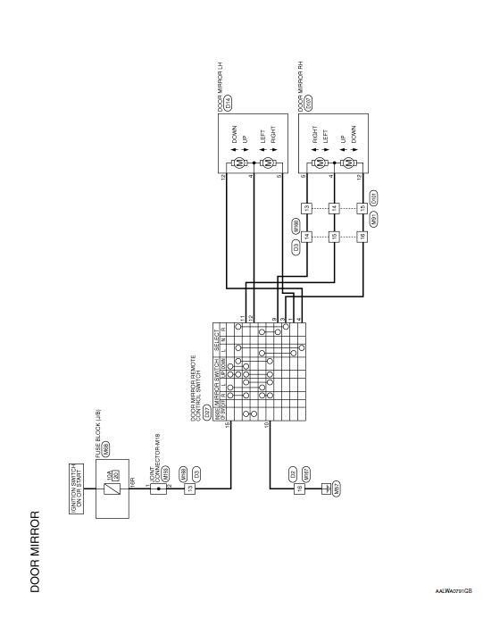
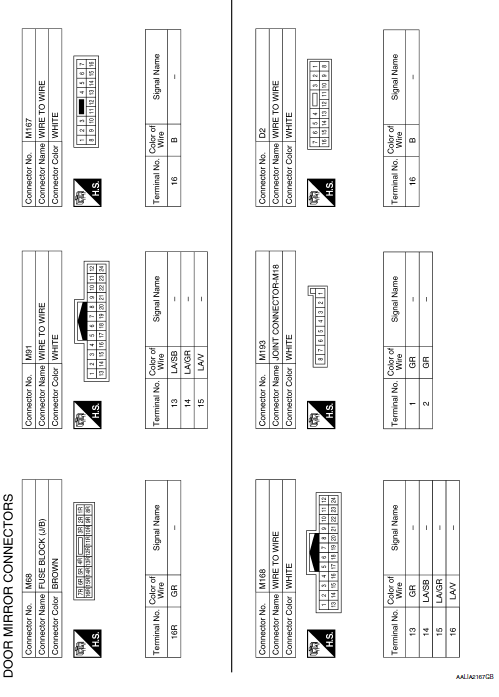
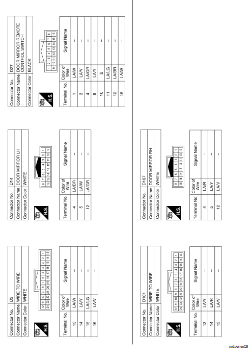
Wiring Diagram


 Inside mirror
Wiring Diagram - With Homelink Universal Transceiver
Wiring Diagram - Without Homelink Universal Transceiver
...
 DTC/circuit diagnosis
DOOR MIRROR REMOTE CONTROL SWITCH (MIRROR SWITCH/
CHANGEOVER SWITCH)
Component Inspection
1.CHECK MIRROR SWITCH & CHANGEOVER SWITCH
Turn ignition switch OFF.
Disconnect door m ...
Other materials:
DTC/circuit diagnosis
U1000 CAN COMM CIRCUIT
Description
Refer to LAN-8, "System Description".
DTC Logic
DTC DETECTION LOGIC
NOTE:
U1000 can be set if a module harness was disconnected and reconnected, perhaps
during a repair. Confirm
that there are actual CAN diagnostic symptoms and a present DTC by p ...
Component parts
Component Parts Location
Combination meter
Engine room right side
Engine room left side
No.
Component part
Description
1
Combination meter (Charge warning lamp)
The IC regulator warning function activates to illuminate the charge
warning
...
Power supply and ground circuit
BCM (BODY CONTROL SYSTEM) (WITH INTELLIGENT KEY SYSTEM)
BCM (BODY CONTROL SYSTEM) (WITH INTELLIGENT KEY SYSTEM) : Diagnosis
Procedure
Regarding Wiring Diagram information, refer to BCS-50, "Wiring Diagram".
1. CHECK FUSE
Check that the following fuse is not blown.
Is the fuse blo ...
