Nissan Rogue Service Manual: Door switch
WITH INTELLIGENT KEY
WITH INTELLIGENT KEY : Component Function Check
1.CHECK FUNCTION
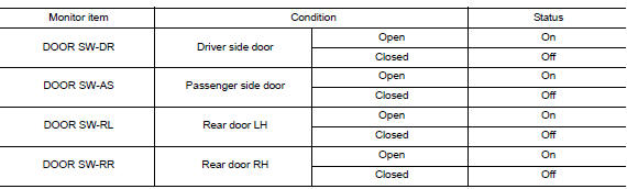
- Select "DOOR LOCK" of "BCM" using CONSULT.
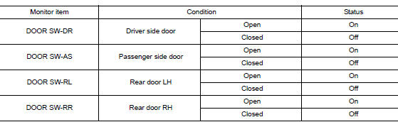
- Select "DOOR SW-DR", "DOOR SW-AS", "DOOR SW-RL", "DOOR SW-RR", in "Data Monitor" mode.
- Check that the function operates normally according to the following conditions.
Is the inspection result normal? YES >> Door switch is OK.
NO >> Refer to RF-34, "WITH INTELLIGENT KEY : Diagnosis Procedure".
WITH INTELLIGENT KEY : Diagnosis Procedure
Regarding Wiring Diagram information, refer to DLK-69, "Wiring Diagram".
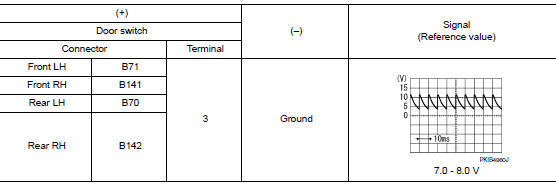
1.CHECK DOOR SWITCH INPUT SIGNAL
- Turn ignition switch OFF.
- Disconnect malfunctioning door switch connector.
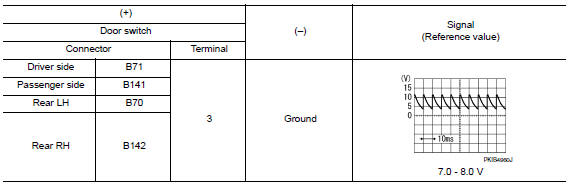
- Check signal between malfunctioning door switch harness connector and ground using oscilloscope.
Is the inspection result normal? YES >> GO TO 3.
NO >> GO TO 2.
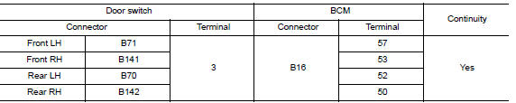
2.CHECK DOOR SWITCH CIRCUIT
- Disconnect BCM connector.
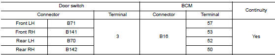
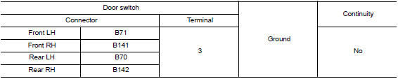
- Check continuity between door switch harness connector and BCM harness connector.
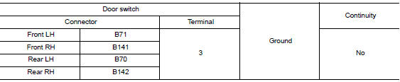
- Check continuity between door switch harness connector and ground.
Is the inspection result normal? YES >> Replace BCM. Refer to BCS-75, "Removal and Installation".
NO >> Repair or replace harness.
3.CHECK DOOR SWITCH
Refer to RF-35, "WITH INTELLIGENT KEY : Component Inspection".
Is the inspection result normal? YES >> GO TO 4.
NO >> Replace malfunctioning door switch. Refer to DLK-269, "Removal and Installation".
4.CHECK INTERMITTENT INCIDENT
Refer to GI-41, "Intermittent Incident".
>> Inspection End.
WITH INTELLIGENT KEY : Component Inspection
1.CHECK DOOR SWITCH
- Turn ignition switch OFF.
- Disconnect malfunctioning door switch connector.
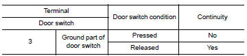
- Check continuity between door switch terminals.
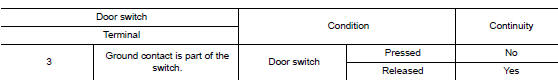
Is the inspection result normal? YES >> Inspection End.
NO >> Replace malfunctioning door switch. Refer to DLK-269, "Removal and Installation".
WITHOUT INTELLIGENT KEY
WITHOUT INTELLIGENT KEY : Description
Detects door open/close condition.
WITHOUT INTELLIGENT KEY : Component Function Check
1.CHECK FUNCTION
- Select "DOOR LOCK" of BCM using CONSULT.
- Select "DOOR SW-DR", "DOOR SW-AS", "DOOR SW-RL", "DOOR SW-RR", in Data Monitor mode.
- Check that the function operates normally according to the following conditions.
Is the inspection result normal? YES >> Door switch is OK.
NO >> Refer to RF-36, "WITHOUT INTELLIGENT KEY : Diagnosis Procedure".
WITHOUT INTELLIGENT KEY : Diagnosis Procedure
Regarding Wiring Diagram information, refer to DLK-293, "Wiring Diagram".
1.CHECK DOOR SWITCH INPUT SIGNAL
- Turn ignition switch OFF.
- Disconnect malfunctioning door switch connector.
- Check signal between malfunctioning door switch harness connector and ground using oscilloscope.
Is the inspection result normal? YES >> GO TO 3.
NO >> GO TO 2.
2.CHECK DOOR SWITCH CIRCUIT
- Disconnect BCM connector.
- Check continuity between door switch harness connector and BCM harness connector.
- Check continuity between door switch harness connector and ground.
Is the inspection result normal? YES >> Replace BCM. Refer to BCS-135, "Removal and Installation".
NO >> Repair or replace harness.
3.CHECK DOOR SWITCH
Refer to RF-35, "WITH INTELLIGENT KEY : Component Inspection".
Is the inspection result normal? YES >> GO TO 4.
NO >> Replace malfunctioning door switch. Refer to DLK-385, "Removal and Installation".
4.CHECK INTERMITTENT INCIDENT
Refer to GI-41, "Intermittent Incident".
>> Inspection End.
WITHOUT INTELLIGENT KEY : Component Inspection
1.CHECK DOOR SWITCH
- Turn ignition switch OFF.
- Disconnect door switch connector.
- Check door switch.
Is the inspection result normal? YES >> Inspection End.
NO >> Replace malfunctioning door switch. Refer to DLK-385, "Removal and Installation".
 Moonroof switch
Description
Transmits switch operation signal to moonroof motor and sunshade motor
assembly.
Diagnosis Procedure
Regarding Wiring Diagram information, refer to RF-17, "Wiring Diagram".
...

Other materials:
Operation
Switch Name and Function
STEERING SWITCH
No.
Switch name
Operation
Description
1
Enter/Up/Down switch
Press
The information display settings can be changed.
2
Display switch
3
Back switch
METER CONTROL SWITCH
No.
Sw ...
P0507 ISC system
Description
The ECM controls the engine idle speed to a specified level through the fine
adjustment of the air, which is let
into the intake manifold, by operating the electric throttle control actuator.
The operating of the throttle valve is
varied to allow for optimum control of the engine ...
Preparation
Special Service Tools
The actual shapes of TechMate tools may differ from those of special service
tools illustrated here.
Tool number
(TechMate No.)
Tool name
Description
KV38100200
(J-26233)
Drift
a: 65 mm (2.56 in) dia.
b: 49 mm (1.93 in) dia.
...