Nissan Rogue Service Manual: DTC/circuit diagnosis
U1000 CAN COMM CIRCUIT
WITH INTELLIGENT KEY
WITH INTELLIGENT KEY : Description
Refer to LAN-8, "System Description".
WITH INTELLIGENT KEY : DTC Logic
DTC DETECTION LOGIC
NOTE: U1000 can be set if a module harness was disconnected and reconnected, perhaps during a repair. Confirm that there are actual CAN diagnostic symptoms and a present DTC by performing the Self Diagnostic Result procedure.
|
CONSULT Display |
DTC Detection Condition |
Possible cause |
| CAN COMM CIRCUIT [U1000] | When any listed module cannot communicate with CAN communication signal continuously for 2 seconds or more with ignition switch ON. | In CAN communication system, any item (or items)
of the following listed below is malfunctioning.
|
WITH INTELLIGENT KEY : Diagnosis Procedure
1. PERFORM SELF DIAGNOSTIC
- Turn ignition switch ON and wait for 2 second or more.
- Check “SELF- DIAG RESULTS”.
Is “CAN COMM CIRCUIT” displayed? YES >> Perform CAN Diagnosis as described in DIAGNOSIS section of CONSULT Operation Manual.
NO >> Refer to GI-41, "Intermittent Incident".
WITHOUT INTELLIGENT KEY
WITHOUT INTELLIGENT KEY : Description
Refer to LAN-8, "System Description".
WITHOUT INTELLIGENT KEY : DTC Logic
DTC DETECTION LOGIC
NOTE: U1000 can be set if a module harness was disconnected and reconnected, perhaps during a repair. Confirm that there are actual CAN diagnostic symptoms and a present DTC by performing the Self Diagnostic Result procedure.
|
CONSULT Display |
DTC Detection Condition |
Possible cause |
| CAN COMM CIRCUIT [U1000] | When any listed module cannot communicate with CAN communication signal continuously for 2 seconds or more with ignition switch ON. | In CAN communication system, any item (or items)
of the following listed below is malfunctioning.
|
WITHOUT INTELLIGENT KEY : Diagnosis Procedure
1. PERFORM SELF DIAGNOSTIC
- Turn ignition switch ON and wait for 2 second or more.
- Check “SELF- DIAG RESULTS”.
Is “CAN COMM CIRCUIT” displayed? YES >> Perform CAN Diagnosis as described in DIAGNOSIS section of CONSULT Operation Manual.
NO >> Refer to GI-41, "Intermittent Incident".
U1010 CONTROL UNIT (CAN)
WITH INTELLIGENT KEY
WITH INTELLIGENT KEY : DTC Logic
DTC DETECTION LOGIC
|
CONSULT Display |
DTC Detection Condition |
Possible cause |
| CAN COMM CIRCUIT [U1010] | BCM detected internal CAN communication circuit malfunction. | BCM |
WITH INTELLIGENT KEY : Diagnosis Procedure
1. REPLACE BCM
When DTC U1010 is detected, replace BCM.
>> Replace BCM. Refer to BCS-75, "Removal and Installation".
WITHOUT INTELLIGENT KEY
WITHOUT INTELLIGENT KEY : DTC Logic
DTC DETECTION LOGIC
|
CONSULT Display |
DTC Detection Condition |
Possible cause |
| CAN COMM CIRCUIT [U1010] | BCM detected internal CAN communication circuit malfunction. | BCM |
WITHOUT INTELLIGENT KEY : Diagnosis Procedure
1. REPLACE BCM
When DTC U1010 is detected, replace BCM.
>> Replace BCM. Refer to BCS-135, "Removal and Installation".
B2614 ACC RELAY CIRCUIT
DTC Logic
DTC DETECTION LOGIC
|
CONSULT Display |
DTC Detection Condition |
Possible cause |
| ACC RELAY CIRCUIT [B2614] | An immediate operation of accessory relay-1 is requested by BCM, but there is no response for more than 1 second. |
|
DTC CONFIRMATION PROCEDURE
1.PERFORM SELF DIAGNOSTIC RESULT
- Turn ignition switch to ON, and wait for 1 second or more.
- Check “Self Diagnosis Result” of “BCM” with CONSULT.
Is DTC B2614 detected? YES >> Go to PCS-64, "Diagnosis Procedure".
NO >> Inspection End.
Diagnosis Procedure
Regarding Wiring Diagram information, refer to PCS-49, "Wiring Diagram".
1.CHECK ACCESSORY RELAY-1 CONTROL SIGNAL VOLTAGE
- Remove accessory relay-1.
- Check voltage between accessory relay-1 connector J-3 and ground.
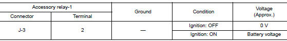
Is the inspection result normal? YES >> GO TO 3.
NO >> GO TO 2.
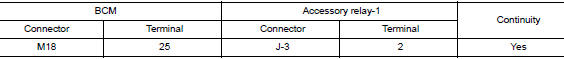
2.CHECK ACCESSORY RELAY-1 CONTROL SIGNAL CIRCUIT
- Turn ignition switch OFF.
- Disconnect BCM connector M18.
- Check continuity between BCM connector M18 and accessory relay-1 connector J-3.
- Check continuity between BCM connector M18 and ground.
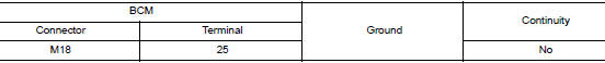
Is the inspection result normal? YES >> Replace BCM. Refer to PCS-76, "Removal and Installation".
NO >> Repair or replace harness or connectors.
3.CHECK ACCESSORY RELAY-1 GROUND CIRCUIT
Check continuity between accessory relay-1 connector J-3 and ground.
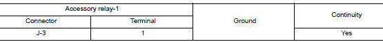
Is the inspection result normal? YES >> Replace accessory relay-1.
NO >> Repair or replace harness or connectors.
B2615 BLOWER RELAY CIRCUIT
DTC Logic
DTC DETECTION LOGIC
|
CONSULT Display |
DTC Detection Condition |
Possible cause |
| BLOWER RELAY CIRCUIT [B2615] | An immediate operation of front blower motor relay is requested by BCM, but there is no response for more than 1 second |
|
DTC CONFIRMATION PROCEDURE
1.PERFORM SELF DIAGNOSTIC RESULT
- Turn ignition switch to ON, and wait for 1 second or more.
- Check “Self Diagnosis Result” of “BCM” with CONSULT.
Is DTC B2615 detected? YES >> Go to PCS-68, "Diagnosis Procedure".
NO >> Inspection End.
Diagnosis Procedure
Regarding Wiring Diagram information, refer to PCS-49, "Wiring Diagram".
1.CHECK FRONT BLOWER MOTOR RELAY CONTROL SIGNAL VOLTAGE
- Remove front blower motor relay.
- Check voltage between front blower motor relay connector J-4 and ground.
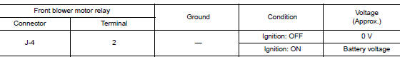
Is the inspection result normal? YES >> GO TO 3.
NO >> GO TO 2.
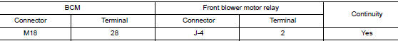
2.CHECK FRONT BLOWER MOTOR RELAY CONTROL SIGNAL CIRCUIT
- Turn ignition switch OFF.
- Disconnect BCM connector M18.
- Check continuity between BCM connector M18 and front blower motor relay connector J-4.
- Check continuity between BCM connector M18 and ground.
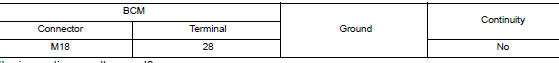
Is the inspection result normal? YES >> Replace BCM. Refer to PCS-76, "Removal and Installation".
NO >> Repair or replace harness or connectors.
3.CHECK FRONT BLOWER MOTOR RELAY GROUND CIRCUIT
Check continuity between front blower motor relay connector J-4 and ground.
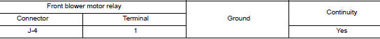
Is the inspection result normal? YES >> Replace front blower motor relay.
NO >> Repair or replace harness or connectors.
B2616 IGNITION RELAY CIRCUIT
DTC Logic
DTC DETECTION LOGIC
|
CONSULT Display |
DTC Detection Condition |
Possible cause |
| IGNITION RELAY CIRCUIT [B2616] | An immediate operation of ignition relay-2 is requested by BCM, but there is no response for more than 1 second. |
|
DTC CONFIRMATION PROCEDURE
1. PERFORM SELF DIAGNOSTIC RESULT
- Turn ignition switch to ON, and wait for 1 second or more.
- Check “Self Diagnosis Result” of “BCM” with CONSULT.
Is DTC B2616 detected? YES >> Refer to PCS-68, "Diagnosis Procedure".
NO >> Inspection End.
Diagnosis Procedure
Regarding Wiring Diagram information, refer to PCS-49, "Wiring Diagram".
1.CHECK IGNITION RELAY-2 CONTROL SIGNAL VOLTAGE
- Remove ignition relay-2.
- Check voltage between ignition relay-2 connector J-1 and ground.
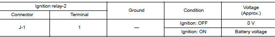
Is the inspection result normal? YES >> GO TO 3.
NO >> GO TO 2.
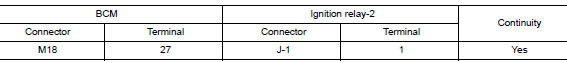
2.CHECK IGNITION RELAY-2 CONTROL SIGNAL CIRCUIT
- Turn ignition switch OFF.
- Disconnect BCM connector M18.
- Check continuity between BCM connector M18 and ignition relay-2 connector J-1.
- Check continuity between BCM connector M18 and ground.
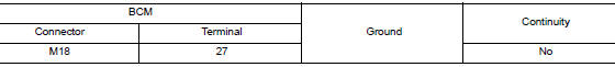
Is the inspection result normal? YES >> Replace BCM. Refer to PCS-76, "Removal and Installation".
NO >> Repair or replace harness or connectors.
3.CHECK IGNITION RELAY-2 GROUND CIRCUIT
Check continuity between ignition relay-2 connector J-1 and ground.
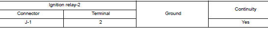
Is the inspection result normal? YES >> Replace ignition relay-2.
NO >> Repair or replace harness or connectors.
B261A PUSH-BUTTON IGNITION SWITCH
DTC Logic
DTC DETECTION LOGIC
|
CONSULT Display |
DTC Detection Condition |
Possible cause |
| PUSH-BUTTON IGNITION SWITCH [B261A] | BCM detects a difference of signal for 1 second or
more between the following information:
|
|
DTC CONFIRMATION PROCEDURE
1. PERFORM SELF DIAGNOSTIC RESULT
- Turn ignition switch to ON, and wait for 1 second or more.
- Check “Self Diagnosis Result” of “BCM” with CONSULT.
Is DTC B261A detected? YES >> Refer to PCS-70, "Diagnosis Procedure".
NO >> Inspection End.
Diagnosis Procedure
Regarding Wiring Diagram information, refer to PCS-49, "Wiring Diagram".
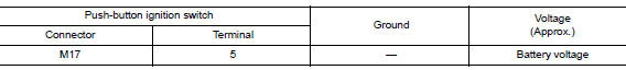
1. CHECK PUSH-BUTTON IGNITION SWITCH OUTPUT SIGNAL (PUSH-BUTTON IGNITION SWITCH)
- Disconnect push-button ignition switch connector.
- Check voltage between push-button ignition switch connector M17 and ground.
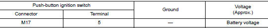
Is the inspection result normal? YES >> GO TO 2.
NO >> GO TO 4.
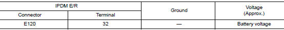
2. CHECK PUSH-BUTTON IGNITION SWITCH OUTPUT SIGNAL (IPDM E/R)
Check voltage between IPDM E/R connector E120 and ground.
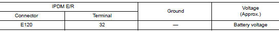
Is the inspection result normal? YES >> GO TO 3.
NO >> Replace IPDM E/R. Refer to PCS-35, "Removal and Installation".
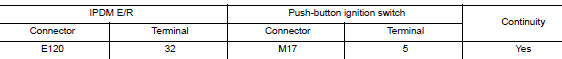
3. CHECK PUSH-BUTTON IGNITION SWITCH CIRCUIT (IPDM E/R)
- Turn ignition switch OFF.
- Disconnect IPDM E/R connector E120 and BCM connector M19.
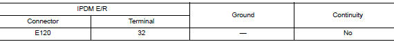
- Check continuity between IPDM E/R connector E120 and push-button ignition switch connector M17.
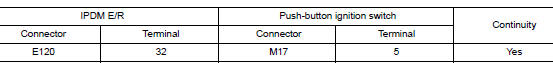
- Check continuity between IPDM E/R connector E120 and ground.
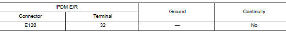
Is the inspection result normal? YES >> Refer to GI-41, "Intermittent Incident".
NO >> Repair or replace harness or connectors.
4. CHECK IGNITION SWITCH OUTPUT SIGNAL (BCM)
Check voltage between BCM connector M19 and ground.
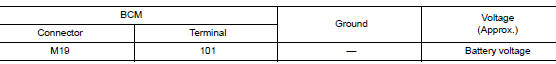
Is the inspection result normal? YES >> GO TO 5.
NO >> Replace BCM. Refer to PCS-76, "Removal and Installation".
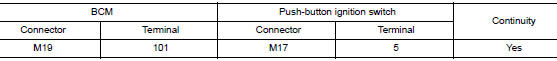
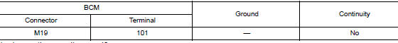
5. CHECK PUSH-BUTTON IGNITION SWITCH CIRCUIT (BCM)
- Turn ignition switch OFF.
- Disconnect BCM connector M19 and IPDM E/R connector E120.
- Check continuity between BCM connector M19 and push-button ignition switch connector M17.
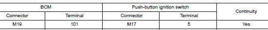
- Check continuity between BCM connector M19 and ground.
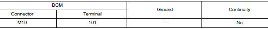
Is the inspection result normal? YES >> Refer to GI-41, "Intermittent Incident".
NO >> Repair or replace harness or connectors.
PUSH-BUTTON IGNITION SWITCH
Component Function Check
1.CHECK FUNCTION
- Select “PUSH SW” in “Data Monitor” of “BCM” with CONSULT.
- Check the push-button ignition switch signal under the following conditions.
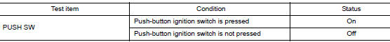
Is the indication normal? YES >> Inspection End.
NO >> Go to PCS-72, "Diagnosis Procedure".
Diagnosis Procedure
Regarding Wiring Diagram information, refer to PCS-49, "Wiring Diagram".
1. CHECK PUSH-BUTTON IGNITION SWITCH OUTPUT SIGNAL (PUSH-BUTTON IGNITION SWITCH)
- Turn ignition switch OFF.
- Disconnect push-button ignition switch connector and IPDM E/R connector E120.
- Check voltage between push-button ignition switch connector M17 and ground.
Is the inspection result normal? YES >> GO TO 3.
NO >> GO TO 2.
2. CHECK PUSH-BUTTON IGNITION SWITCH CIRCUIT (BCM)
- Disconnect BCM connector M19.
- Check continuity between BCM connector M19 and push-button ignition switch connector M17.
- Check continuity between BCM connector M19 and ground.
Is the inspection result normal? YES >> Replace BCM. Refer to PCS-76, "Removal and Installation".
NO >> Repair or replace harness or connectors.
3. CHECK IGNITION SWITCH OUTPUT SIGNAL (IPDM E/R)
Check voltage between IPDM E/R connector E120 and ground.
Is the inspection result normal? YES >> GO TO 5.
NO >> GO TO 4.
4. CHECK PUSH-BUTTON IGNITION SWITCH CIRCUIT (IPDM E/R)
- Disconnect BCM connector M19.
- Check continuity between IPDM E/R connector E120 and push-button ignition switch connector M17.
- Check continuity between IPDM E/R connector E120 and ground.
Is the inspection result normal? YES >> Replace IPDM E/R. Refer to PCS-35, "Removal and Installation".
NO >> Repair or replace harness or connectors.
5.CHECK PUSH-BUTTON IGNITION SWITCH GROUND CIRCUIT
Check continuity between push-button ignition switch connector M17 and ground.
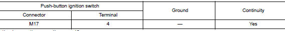
Is the inspection result normal? YES >> GO TO 6.
NO >> Repair or replace harness or connectors.
6.CHECK PUSH-BUTTON IGNITION SWITCH
Refer to PCS-73, "Component Inspection".
Is the inspection result normal? YES >> Refer to GI-41, "Intermittent Incident".
NO >> Replace push-button ignition switch. Refer to PCS-77, "Removal and Installation".
Component Inspection
1.CHECK PUSH-BUTTON IGNITION SWITCH
- Turn ignition switch OFF.
- Disconnect push-button ignition switch connector.
- Check continuity between push-button ignition switch terminals.
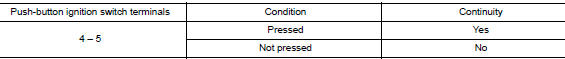
Is the inspection result normal? YES >> Inspection End.
NO >> Replace push-button ignition switch.
 Basic inspection
DIAGNOSIS AND REPAIR WORK FLO
Work Flow
OVERALL SEQUENCE
DETAILED FLOW
1.GET INFORMATION FOR SYMPTOM
Get detailed information from the customer about the symptom (the
condition an ...
 Symptom diagnosis
PUSH-BUTTON IGNITION SWITCH DOES NOT OPERATE
Description
Check that vehicle Operating Conditions are as listed in “Conditions of
Vehicle” below before starting Diagnosis
Procedure. Make sure ...
Other materials:
P0117, P0118 ECT sensor
DTC Description
DTC DETECTION LOGIC
DTC No.
CONSULT screen terms
(Trouble diagnosis content)
DTC detecting condition
P0117
ECT SEN/CIRC
(Engine coolant temperature sensor 1 circuit
low)
An excessively low voltage from the engine coolant temperature
sensor i ...
Front bumper
Exploded View
Front bumper fascia side
bracket (RH)
Front bumper reinforcement
support (RH)
Front bumper reinforcement
Front energy absorber
Front lower grille
Front fog lamp (RH) (if equipped)
Front bumper fascia
Front bumper fascia finisher
(RH) (if equipped)
...
Rapid air pressure loss
Rapid air pressure loss or a “blow-out” can occur
if the tire is punctured or is damaged due to
hitting a curb or pothole. Rapid air pressure loss
can also be caused by driving on under-inflated
tires.
Rapid air pressure loss can affect the handling
and stability of the vehicle, especial ...