Nissan Rogue Service Manual: Fluid cooler hose
Exploded View
COMPONENT PARTS LOCATION
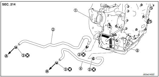
- Transaxle assembly
- Fluid cooler hose A
- Hose clamp
- Fluid cooler hose B
- CVT oil warmer
- To radiator
 : Always replace after every
disassembly.
: Always replace after every
disassembly.
Removal and Installation
REMOVAL
NOTE: When removing components such as hoses, tubes/lines, etc., cap or plug openings to prevent fluid from spilling.
- Remove engine under cover. Refer to EXT-37, "ENGINE UNDER COVER : Removal and Installation".
- Remove fender protector side cover. Refer to EXT-28, "FENDER PROTECTOR : Exploded View".
- Remove fluid cooler hoses.
INSTALLATION
Installation is in the reverse order of removal.
CAUTION:
- Do not reuse hose clamp.
- Securely install fluid cooler hose A clip to the radiator core support.
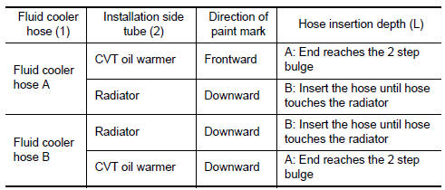
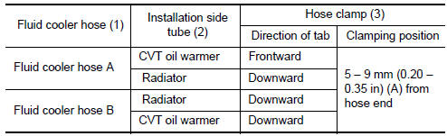
- Refer to the followings when installing fluid cooler hoses.
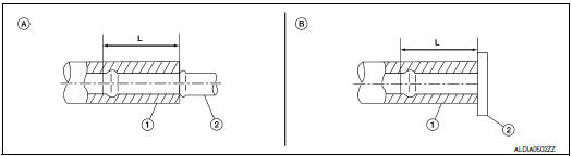
- Refer to the followings when installing hose clamps.
CAUTION: Hose clamp should not interfere with the bulge of tube.
Inspection
INSPECTION AFTER INSTALLATION
Check for CVT fluid leakage and check CVT fluid level. Refer to TM-190, "Inspection".
 Water hose
Exploded View
Water outlet
Hose clamp
Water hose A
Clip
CVT oil warmer
Transaxle assembly
Water hose B
Heater thermostat
Water hose C
: Always replace after every
di ...
 CVT oil warmer
Exploded View
Transaxle assembly
CVT oil warmer
: N·m (kg-m, in-lb)
Removal and Installation
REMOVAL
WARNING:
Do not remove the radiator cap when the engine is hot. Serious burns co ...
Other materials:
EVAP canister filter
Exploded View
EVAP canister vent control valve hose
Canister drain hose
Plug
EVAP canister filter
Front
Removal and Installation
REMOVAL
Disconnect EVAP canister vent control valve hose from EVAP
canister filter.
Disconnect canister drain hose from E ...
P0500 VSS
Description
ECM receives vehicle speed signals from two different paths via CAN
communication line: One is from the
ABS actuator and electric unit (control unit) via the combination unit and the
other is from TCM.
DTC Description
DTC DETECTION LOGIC
DTC No.
CONSULT screen terms
...
DTC/circuit diagnosis
U1000 CAN COMM CIRCUIT
Description
Refer to LAN-8, "System Description".
DTC Logic
DTC DETECTION LOGIC
CONSULT Display
DTC Detection Condition
Possible Cause
CAN COMM CIRCUIT
[U1000]
When IPDM E/R cannot communicate with CAN communication
sig ...