Nissan Rogue Service Manual: Overdrive control switch
Component Function Check
1.CHECK O/D OFF INDICATOR LAMP FUNCTION
Check O/D OFF indicator lamp turns ON for approx. 2 seconds when ignition switch turns ON.
Is the inspection results normal? YES >> GO TO 2.
NO >> Go to TM-181, "Diagnosis Procedure".
2.CHECK OVERDRIVE CONTROL SWITCH FUNCTION
- Shift the selector lever to ŌĆ£DŌĆØ position.
- Check that O/D OFF indicator lamp turns ON/OFF when overdrive control switch is operated.
Is the inspection results normal? YES >> INSPECTION END
NO >> Go to TM-178, "Diagnosis Procedure".
Diagnosis Procedure
1.CHECK OVERDRIVE CONTROL SWITCH CIRCUIT
- Turn ignition switch OFF.
- Disconnect CVT shift selector connector.
- Turn ignition switch ON.
- Check voltage between CVT shift selector harness connector terminals.
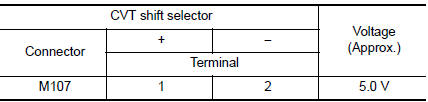
Is the inspection result normal? YES >> GO TO 2.
NO >> GO TO 4.
2.CHECK CVT SHIFT SELECTOR CIRCUIT
Check continuity between CVT shift selector harness connector terminals.
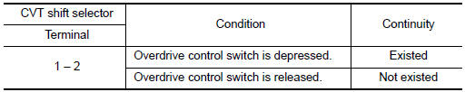
Is the inspection result normal? YES >> GO TO 7.
NO >> GO TO 3.
3.CHECK OVERDRIVE CONTROL SWITCH
Check overdrive control switch. Refer to TM-179, "Component Inspection".
Is the inspection result normal? YES >> Repair CVT shift selector assembly. Refer to TM-194, "Removal and Installation".
NO >> Replace selector lever knob. Refer to TM-194, "Removal and Installation".
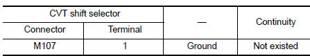
4.CHECK GROUND CIRCUIT
Check continuity between CVT shift selector harness connector terminal and ground.
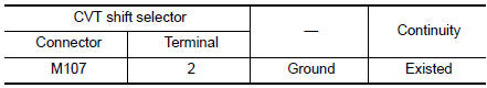
Is the inspection result normal? YES >> GO TO 5.
NO >> Repair or replace malfunctioning parts.
5.CHECK CIRCUIT BETWEEN CVT SHIFT SELECTOR AND COMBINATION METER (PART 1)
- Turn ignition switch OFF.
- Disconnect combination meter connector.
- Check continuity between CVT shift selector harness connector terminal and combination meter harness connector terminal.
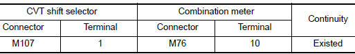
the inspection result normal? YES >> GO TO 6.
NO >> Repair or replace malfunctioning parts.
6.CHECK CIRCUIT BETWEEN CVT SHIFT SELECTOR AND COMBINATION METER (PART 2)
Check continuity between CVT shift selector harness connector terminal and ground.
Is the inspection result normal? YES >> GO TO 7.
NO >> Repair or replace malfunctioning parts.
7.CHECK COMBINATION METER INPUT/OUTPUT SIGNAL
- Connect all of disconnected connectors.
- Turn ignition switch ON.
- Select ŌĆ£Data MonitorŌĆØ in ŌĆ£METER/M&AŌĆØ.
- Select ŌĆ£O/D OFF SWŌĆØ.
- Check that ŌĆ£O/D OFF SWŌĆØ turns ON/OFF when overdrive control switch is operated. Refer to MWI-24, "Reference Value".
Is the inspection result normal?
YES >> Check intermittent incident. Refer to GI-41, "Intermittent Incident".
NO >> Replace combination meter. Refer to MWI-82, "Removal and Installation".
Component Inspection
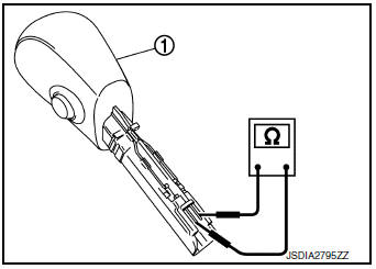
1.CHECK OVERDRIVE CONTROL SW
Check continuity between wires of shift selector knob 1.
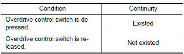
Is the inspection result normal? YES >> INSPECTION END
NO >> Replace shift selector knob. Refer to TM-194, "Removal and Installation".
 Main power supply and ground circuit
Diagnosis Procedure
1.CHECK TCM POWER CIRCUIT (PART 1)
Turn ignition switch OFF.
Disconnect TCM connector.
Check voltage between TCM harness connector terminals and ground.
...
 O/D off indicator lamp
Component Function Check
1.CHECK O/D OFF INDICATOR LAMP FUNCTION
Check O/D OFF indicator lamp turns ON for approx. 2 seconds when ignition
switch turns ON.
Is the inspection results normal?
YE ...
Other materials:
USB (Universal Serial Bus) Connection Port (models with Navigation System)
(if so equipped)
USB (Universal Serial Bus) Connection Port (models with Navigation System)
Connecting a device to the USB
Connection Port
WARNINGDo not connect, disconnect, or operate the
USB device while driving. Doing so can be
a distraction. If distracted you could lose
control of your ...
Spiral cable
Exploded View
Combination switch
Steering angle sensor
Spiral cabl
Removal and Installation
WARNING:
Before servicing the SRS, turn ignition switch OFF, disconnect
both battery terminals then wait at
least three minutes.
Do not use the air tools or electric t ...
Fuel recommendation
Use unleaded regular gasoline with an octane
rating of at least 87 AKI (Anti-Knock Index) number
(Research octane number 91).
CAUTION
Only vehicles with the E-85 filler door
label can operate on E-85. Fuel system
or other damage can occur if E-85 is
used in vehicles t ...