Nissan Rogue Owners Manual: Passenger compartment
| CAUTION Never use a fuse of a higher or lower amperage rating than specified on the fuse box cover. This could damage the electrical system or cause a fire. |
If any electrical equipment does not operate, check for an open fuse.
NOTE: The fuse box is located on the driver’s side of the instrument panel.
- Be sure the ignition switch and the headlight switch are OFF.
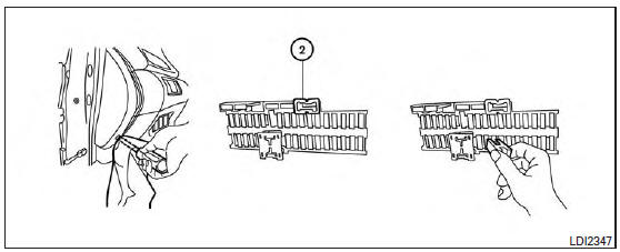
- Remove the fuse box cover with a suitable tool. Use a cloth to avoid damaging the trim.
- Locate the fuse that needs to be replaced.
- Remove the fuse with the fuse puller 2 .
- If the fuse is open A , replace it with an equivalent good fuse B .
- Push the fuse box cover to install.
If a new fuse also opens, have the electrical system checked and repaired by a NISSAN dealer.
Extended storage switch
If any electrical equipment does not operate, remove the extended storage switch and check for an open fuse.
NOTE: The extended storage switch is used for long term vehicle storage. Even if the extended storage switch is broken it is not necessary to replace it. Replace only the open fuse in the switch with a new fuse. How to replace the extended storage switch:
- To remove the extended storage switch, be sure the ignition switch is in the OFF or LOCK position.
- Be sure the headlight switch is in the OFF position.
- Remove the fuse box cover.
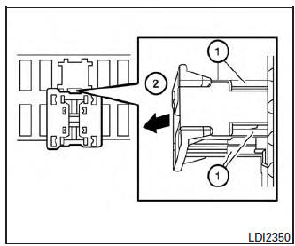
- Pinch the locking tabs 1 found on each side of the storage switch.
- Pull the storage switch straight out from the fuse box 2 .
 Engine compartment
CAUTIONNever use a fuse of a higher or lower
amperage rating than specified on the
fuse box cover. This could damage the
electrical system or cause a fire.
Two types of fuses ...
 Battery replacement
CAUTIONBe careful not to allow children to swallow
the battery or removed parts.
...
Other materials:
Removal and installation
CHASSIS CONTROL MODULE
Exploded View
Steering member
Chassis control module
Front
Removal and Installation
CAUTION:
When replacing chassis control module, configuration of chassis control module
is required. Refer to
DAS-205, "Work Procedure".
REMOVAL
NOTE:
...
Component parts
METER SYSTEM
METER SYSTEM : Component Parts Location
Vehicle front
View of the fuel pump and fuel level
sensor inspection hole covers with
the rear seat removed.
View of front engine assembly
No.
Component
Function
1
Combination me ...
Steering gear and linkage
Inspection
BOOT
Check boot for cracks. Replace if any damage is found.
OUTER SOCKET AND INNER SOCKET
Boot
Check boot for cracks, and replace it if a malfunction is
detected.
Gear Housing
Check gear housing for damage and scratches (inner wall). Replace
if there are a ...