Nissan Rogue Service Manual: Sample/Wiring Diagram -Example-
Each section includes wiring diagrams.
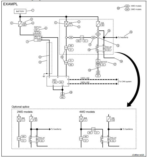
Description
| Number | Item | Description |
| 1 | Power supply |
|
| 2 | Fuse |
|
| 3 | Current rating of fusible link/fuse |
|
| 4 | Number of fusible link/ fuse |
|
| 5 | Fusible link |
|
| 6 | Connector number |
|
| 7 | Switch |
|
| 8 | Circuit (Wiring) |
|
| 9 | Shielded line |
|
| 10 | Connectors |
|
| 11 | Option abbreviation |
|
| 12 | Relay |
|
| 13 | Optional splice |
|
| 14 | Splice |
|
| 15 | System branch |
|
| 16 | Page crossing |
|
| 17 | Component name |
|
| 18 | Terminal number |
|
| 19 | Ground (GND) |
|
| 20 | Explanation of option description |
|
 ”.
”. ” means the splice.
SWITCH POSITIONS
Switches are shown in wiring diagrams as if the vehicle is in the “normal” condition.
A vehicle is in the “normal” condition when:
- ignition switch is “OFF”
- doors, hood and trunk lid/back door are closed
- pedals are not depressed
- parking brake is released
MULTIPLE SWITCH
The continuity of multiple switch is described in two ways as shown below.
- The switch chart is used in schematic diagrams.
- The switch diagram is used in wiring diagrams.
 Connector Symbols
Most of connector symbols in wiring diagrams are shown from the terminal
side.
Connector symbols shown from the terminal side are enclosed by
a single line and followed by the direction ...
 Connector Information
HOW TO USE CONNECTOR INFORMATION
Description
Number
Item
Description
1
Connector number
Alphabetic characters show to which harness the connector is
pla ...
Other materials:
Symptom diagnosi
NOISE, VIBRATION, AND HARSHNESS (NVH) TROUBLESHOOTING
NVH troubleshooting - engine noise
Valve mechanism
Intake and exhaust valve
Water pump
Timing chain
Drive belt
Rotation mechanism
Tappet noise
Camshaft bearing noise
&nb ...
Air breather
Exploded View
Air breather
Air breather hose
Air breather tube
Transaxle assembly
: Vehicle front
Removal and Installation
REMOVAL
Remove air cleaner and air duct. Refer to EM-24, "Removal and
Installation".
Remove air breather hose from transaxle a ...
System description
COMPONENT PARTS
Component Parts Location
IPDM E/R
Engine compartment (LH)
SYSTEM
RELAY CONTROL SYSTEM
RELAY CONTROL SYSTEM : System Description
SYSTEM DIAGRAM
DESCRIPTION
IPDM E/R activates the internal control circuit to perform the relay ON-OFF
control according to t ...