Nissan Rogue Service Manual: Fender protector
FENDER PROTECTOR
FENDER PROTECTOR : Exploded View
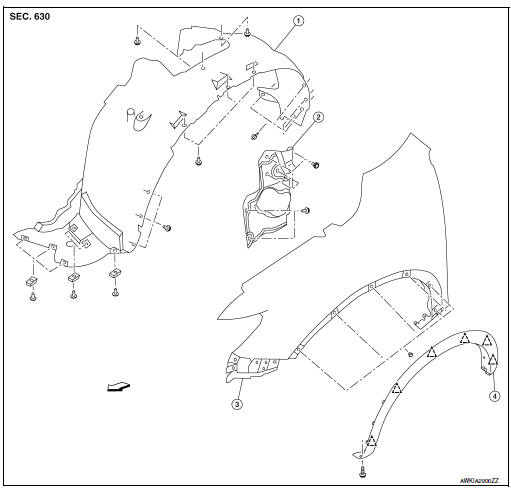
- Front fender protector
- Engine side cover
- Front fender
- Over fender
 Clip
Clip
 Front
Front
FENDER PROTECTOR : Removal and Installation
REMOVAL
- Remove wheel and tire using power tool. Refer to WT-60, "Removal and Installation".
- Remove front over fender molding. Refer to EXT-30, "FRONT OVER FENDER : Removal and Installation".
- Remove front under cover. Refer to EXT-16, "Exploded View".
- Remove sill molding screw. Refer to EXT-35, "Exploded View - Center Mudguard".
- Remove engine side cover.
- Release front fender protector clips and remove front fender protector.
INSTALLATION
Installation is in the reverse order of removal.
REAR WHEEL HOUSE PROTECTOR
REAR WHEEL HOUSE PROTECTOR : Exploded View
- Rear fender
- Rear wheel house protector
- rear over fender molding
Clip
Front
REAR WHEEL HOUSE PROTECTOR : Removal and Installation
REMOVAL
- Remove rear wheel house protector clip and screws.
- Remove rear wheel house protector nuts and rear wheel house protector.
INSTALLATION
Installation is in the reverse order of removal.
 Cowl top
Exploded View
Cowl top side trim cover (RH)
Cowl top cover screen
Cowl top cover seal
EPT seal
Cowl top cover plug
Cowl top cover
Cowl top cover mask
Cowl top ex ...
 Over fender
FRONT OVER FENDER
FRONT OVER FENDER : Exploded View
Front fender protector
Front fender
Front over fender molding
Clip
FRONT OVER FENDER : Removal and Installation
REM ...
Other materials:
Symptom diagnosis
CVT CONTROL SYSTEM
Symptom Table
The diagnosis item number indicates the order of check. Start checking
in the order from 1.
Perform diagnoses of symptom table 1 before symptom table 2.
Symptom Table 1
Symptom Table 2
...
Wiring diagram
ENGINE CONTROL SYSTEM
Wiring Diagram
...
Key switch signal circuit (without intelligent key)
Description
Transmits a key switch signal to the BCM.
Component Function Check
1. CHECK BCM INPUT SIGNAL
Select "Data Monitor" for "BCM" and check the "KEY ON SW" monitor value.
Is the inspection result normal?
YES >> Inspection End.
NO >> Refer ...